
Sample -hold circuit

a sample-hold circuit and sample-holding technology, applied in the current field, can solve the problems of increased power consumption, aggravated droop, and restricted design parameters, and achieve the effects of reducing droop and feed, and reducing droop caused by leakage curren

Inactive Publication Date: 2006-06-01
FUJITSU LTD
View PDF5 Cites 8 Cited by
  • Summary
  • Abstract
  • Description
  • Claims
  • Application Information

AI Technical Summary

Benefits of technology

[0019] The objective of the present invention is to reduce the droop, namely a variation in the hold voltage attributable to the leakage current of the transistor, and the feed through, namely the leakage of the input analog voltage, during the hold period, thereby providing a sample-hold circuit suitable for high speed operation while maintaining a wider freedom of design than that of a prior art circuit, in light of the afore-mentioned problems.
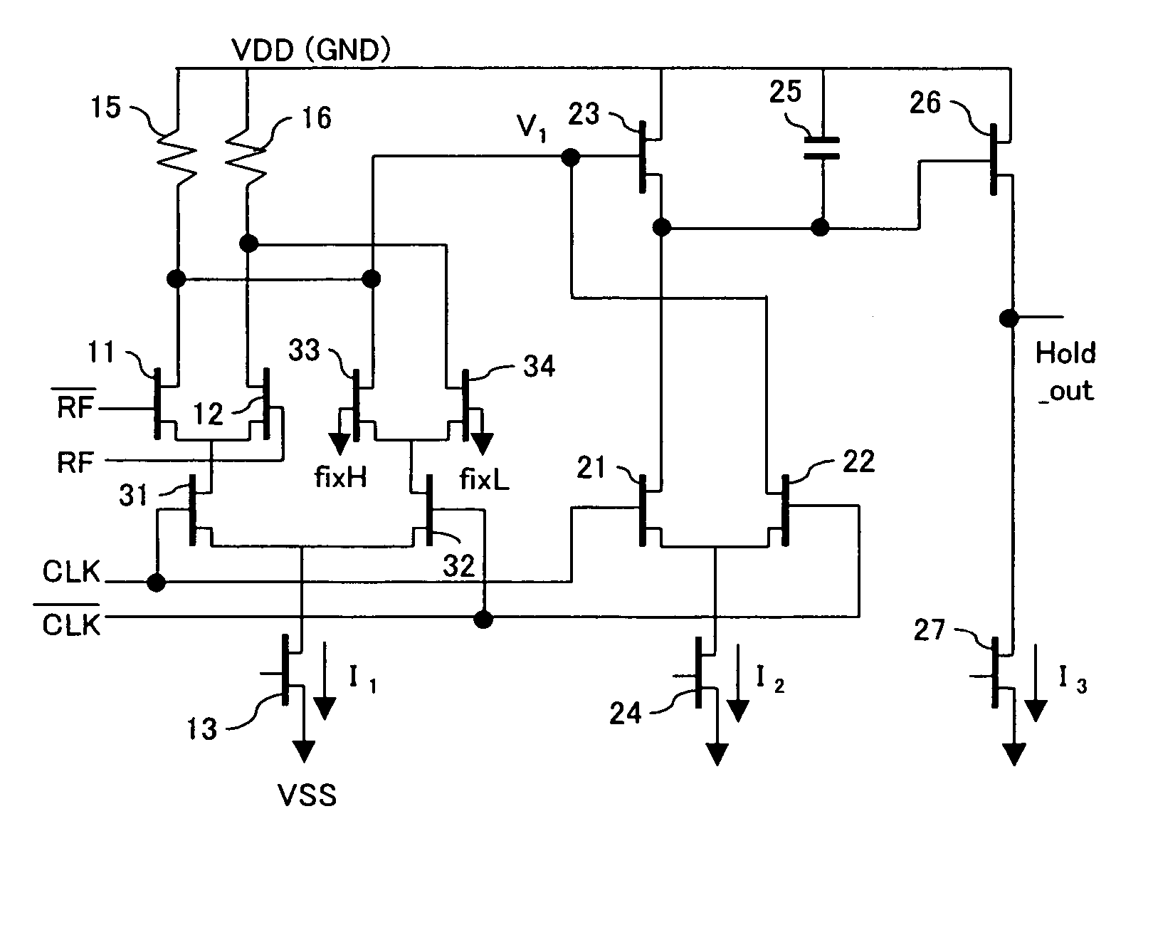
[0020] The sample-hold circuit according to the present invention comprises: a core section where the amplified output of the input analog signal by said preamplifier is applied as an input, and a voltage corresponding to the variation in the input analog signal is output during the sampling period, and the value of the voltage corresponding to the amplified output at the time of the transition of the sample clock signal is held and output during the hold period; and a current switching circuit which is connected to the output pin of the preamplifier during the hold period and enables the current which flows into the first transistor, comprised in the preamplifier, during the sampling period, to flow into another second transistor to apply a constant voltage as an input to the core section. This enables reduction in the droop and feed through. In addition, the droop caused by the leakage current of the transistor can be reduced by connecting a diode, which has reverse polarity to that of the hold voltage of the capacitance which holds the voltage within the core section. Furthermore, the droop caused by the leakage current can be further reduced by arranging the differential transistor pair which configures the current switching circuit inside the core section into a two-stage series configuration, thereby realizing a sample-hold circuit which can be operated at high speeds, has high accuracy, and has low-noise characteristics while maintaining a wider freedom of circuit design.

Problems solved by technology

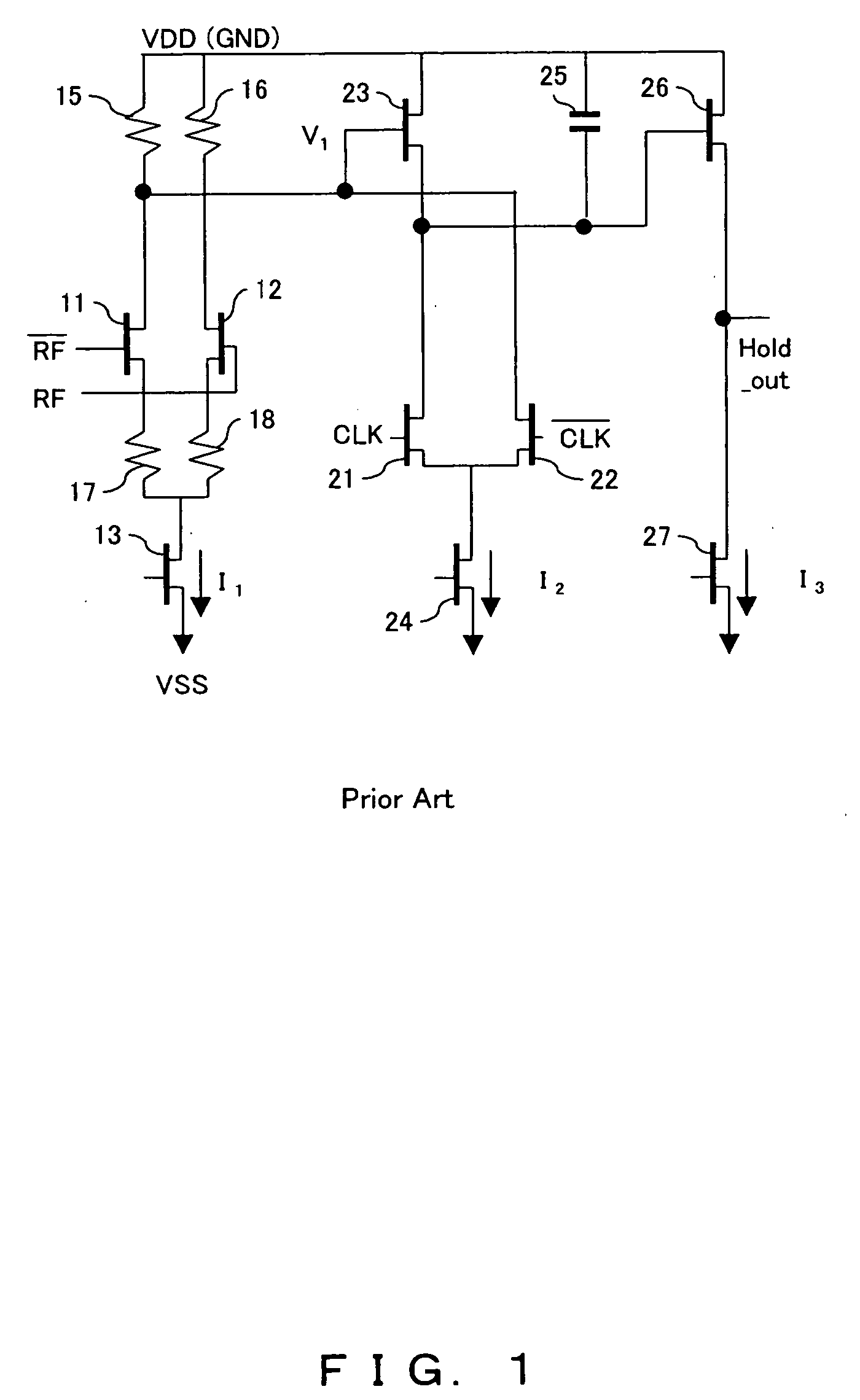
However, in the second example of the prior art, although the feed through is suppressed, there exists a problem in that the current source current I1 does not flow into the resistor 15 during the hold period, and compared with the first example of the prior art, the potential V1 during the hold period is increased by R1×I1, and thus the droop aggravated.
However, if I2 is increased, the switching characteristics of the transistors 21 and 22, which comprise the differential transistor pair wherein current switching is performed, deteriorate, and power consumption increases.
Therefore, there is an additional problem in that design parameters are restricted.

Method used


Image

  • Sample -hold circuit
  • Sample -hold circuit
  • Sample -hold circuit

Examples


first embodiment

[0031]FIG. 4 is the principle configuration block diagram of a sample-hold circuit according to the present invention. This diagram shows the principle configuration of the sample-hold circuit comprising a preamplifier 1 to which the input analog signal is applied and corresponds to the sample-hold circuit according to the present invention, later described.

[0032] In FIG. 4, the amplified output of the input analog signal from the preamplifier 1 is applied as an input to a core section 2 which outputs a voltage corresponding to the variation in the input analog signal during the sampling period, holds the value of the voltage corresponding to the amplified output at the time of transition of the sample clock signal, and outputs the held value during the hold period.

[0033] The current switching circuit 3 is connected to the output pin of the preamplifier and enables the current flowing into the first transistor comprised within the preamplifier 1 during the sampling period to flow i...

second embodiment

[0037] The sample-hold circuit which partially corresponds to the sample-hold circuit later described comprises a preamplifier to which the input analog signal is applied and a core section to which the output of the preamplifier is applied, as in FIG. 4. In addition, the core section of the sample-hold circuit is comprised of first and second transistors, which are connected in series and to each gate of which the sample clock signal is applied, and a capacitance which is connected to one of the first and second transistors and holds the value of the voltage corresponding to the output of the preamplifier at the time of the transition of the sample clock signal.

[0038] Similarly, another sample-hold circuit, which partially corresponds to the second embodiment, described later, comprises a preamplifier and a core section. The core section comprises a capacitance which holds the value of the voltage corresponding to the output of the preamplifier at the time of the transition of the ...

third embodiment

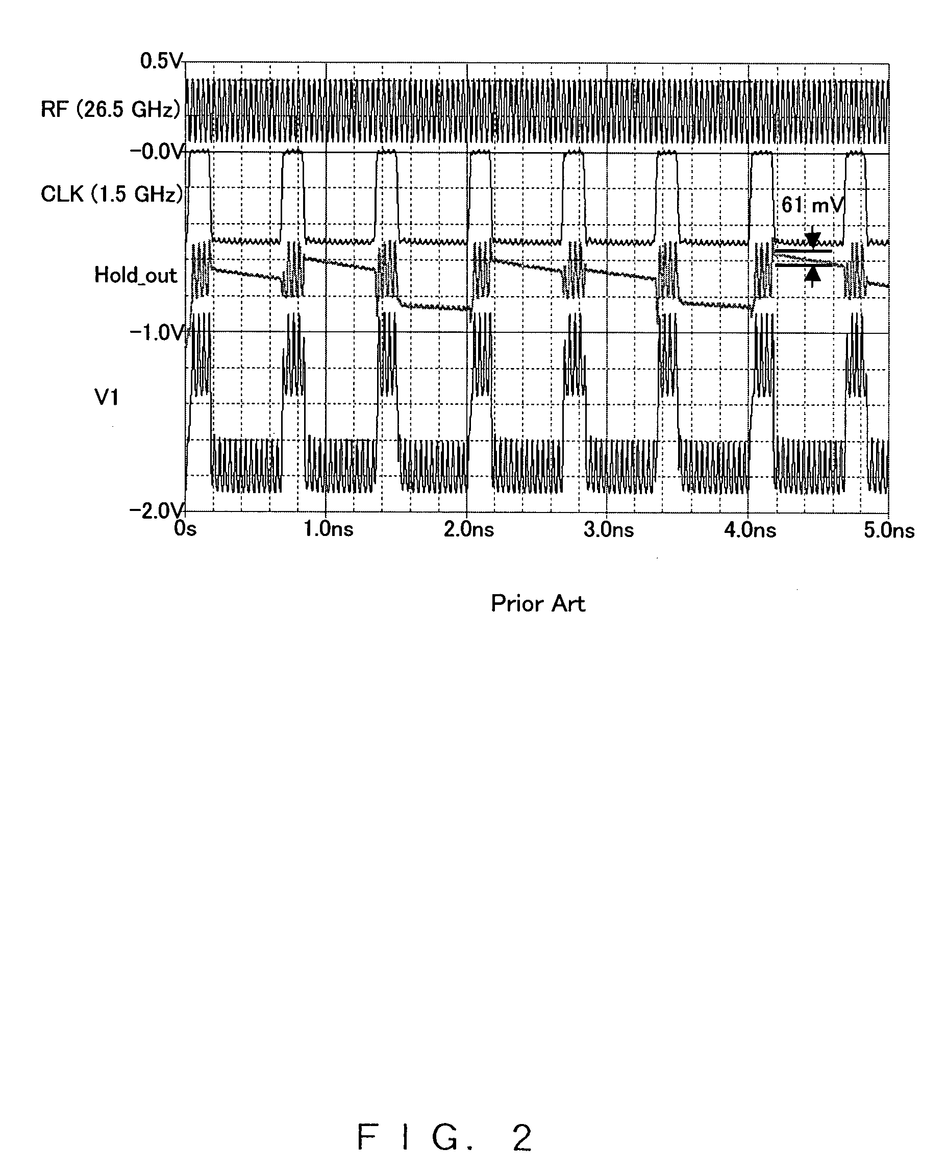
[0062]FIG. 10 is the simulation result of the third embodiment in FIG. 7. The maximum value of the droop is 33 mV, and it can be understood that the droop is improved by 46%, compared to that in FIG. 2. In addition, the improvement effect on the feed through is evident.


PUM


Abstract

A sample-hold circuit, which reduces droop and feed through and is suitable for high-speed operation while maintaining a wider freedom of design parameters, comprising a preamplifier to which an input analog signal is applied, a core section which outputs a voltage corresponding to the variation of an output from the preamplifier during the sampling period and holds the voltage corresponding to the output from the preamplifier during the hold period initiated by a transition of a clock signal, and a current switching circuit which is connected to the output pin of the preamplifier and enables the current flowing into the first transistor within the preamplifier during the sampling period to flow into another second transistor to apply a constant potential as an input to the core section.

Description

CROSS-REFERENCE TO RELATED APPLICATIONS [0001] This application is based upon and claims the benefit of priority from the prior Japanese Patent Application No. 2004-346934 filed on Nov. 30, 2004, the entire contents of which are incorporated herein by reference. BACKGROUND OF THE INVENTION [0002] 1. Field of the Invention [0003] The present invention relates to a sample-hold circuit used, for example, for an analog digital converter or a wireless communication receiving circuit. More specifically, the present invention relates to a current switching source-follower-type sample-hold circuit wherein droop, namely a variation in a hold voltage caused by the leakage current of a transistor, and feed through, namely an influence of an input analog voltage on the hold voltage during a hold period, can be reduced. [0004] 2. Description of the Related Art [0005]FIG. 1 is a circuit diagram according to a first example of the prior art of a sample-hold circuit of the current switching source-...

Claims


Application Information

Patent Timeline
Patent Type & Authority Applications(United States)
IPC IPC(8): G11C27/02
CPCG11C27/02G11C27/028
Inventor NAKASHA, YASUHIROHIROSE, TATSUYA
Owner FUJITSU LTD
Learn More