Image reading apparatus including reading unit having conductive abutting portion

Inactive Publication Date: 2009-03-10
CANON KK
View PDF11 Cites 7 Cited by
  • Summary
  • Abstract
  • Description
  • Claims
  • Application Information

AI Technical Summary

Benefits of technology

[0018]It is a primary object of the present invention to provide an image reading apparatus capable of preventing triboelectrification between a reading unit and an original placing member.

Problems solved by technology

This type of image sensor, however, has a such a problem that a focal depth is small, and the resolution declines due to a fluctuation of distance between a platen glass and the image sensor.
According to this method, however, triboelectrification might occur due to a frictional slide between the abutting member and the platen glass.
Then, when electric charges generated are discharged, electrostatic noises enter the image sensor disposed within an image reading unit and an electric circuit, with the result that an image output might be disturbed.
In this case, however, the uniformity of an output image declines due to the discharge noises entering the reading signals.
Further, the de-electrifying cloth is easy to fall and fold down because of being used for a long period of time, and the effect thereof does not continue.
Moreover, a conveying resistance increases due to the de-electrifying cloth, and hence a drive load rises, with the result that the apparatus architecture becomes hard to downsize and the electric power consumption gets difficult to decrease.
Further, Japanese Patent Application Laid-Open No. 07-193689 does not particularly deal with an electric resistance value of the abutting member and a de-electrification preventing process, nor does it show any measure against the occurrence of the image noises due to the discharge of the static electricity described above.
Furthermore, U.S. Pat. No. 6,008,485 exemplifies a ball bearing composed of a metallic material as an abutting member but has a problem, wherein the ball bearing is hard to control the gap related to the abutting member, and requires an additive such as an oil for lubricating the drive of the bearing, which is unpreferable in terms of contamination.

Method used


Image

  • Image reading apparatus including reading unit having conductive abutting portion
  • Image reading apparatus including reading unit having conductive abutting portion
  • Image reading apparatus including reading unit having conductive abutting portion

Examples


first embodiment

[0027]FIGS. 1 through 3 show the present invention.

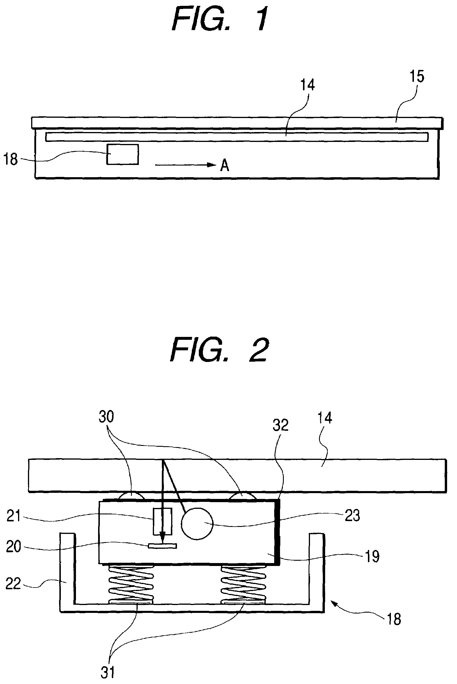
[0028]FIG. 1 is a schematic sectional view showing an image reading apparatus in the first embodiment. Referring to FIG. 1, a platen glass 14 as a light shielding member is disposed, and a press plate 15 for pressing, against on the platen glass 14, an unillustrated original placed on the platen glass 14 is provided above the platen glass 14.

[0029]Further, an original reading unit 18 defined as an image reading unit is disposed under the platen glass 14. The original reading unit 18 reads an image of the original in such a way that an unillustrated driving device moves the original reading unit 18 in an auxiliary scan direction indicated by an arrowhead A with respect to the original placed on the platen glass 14.

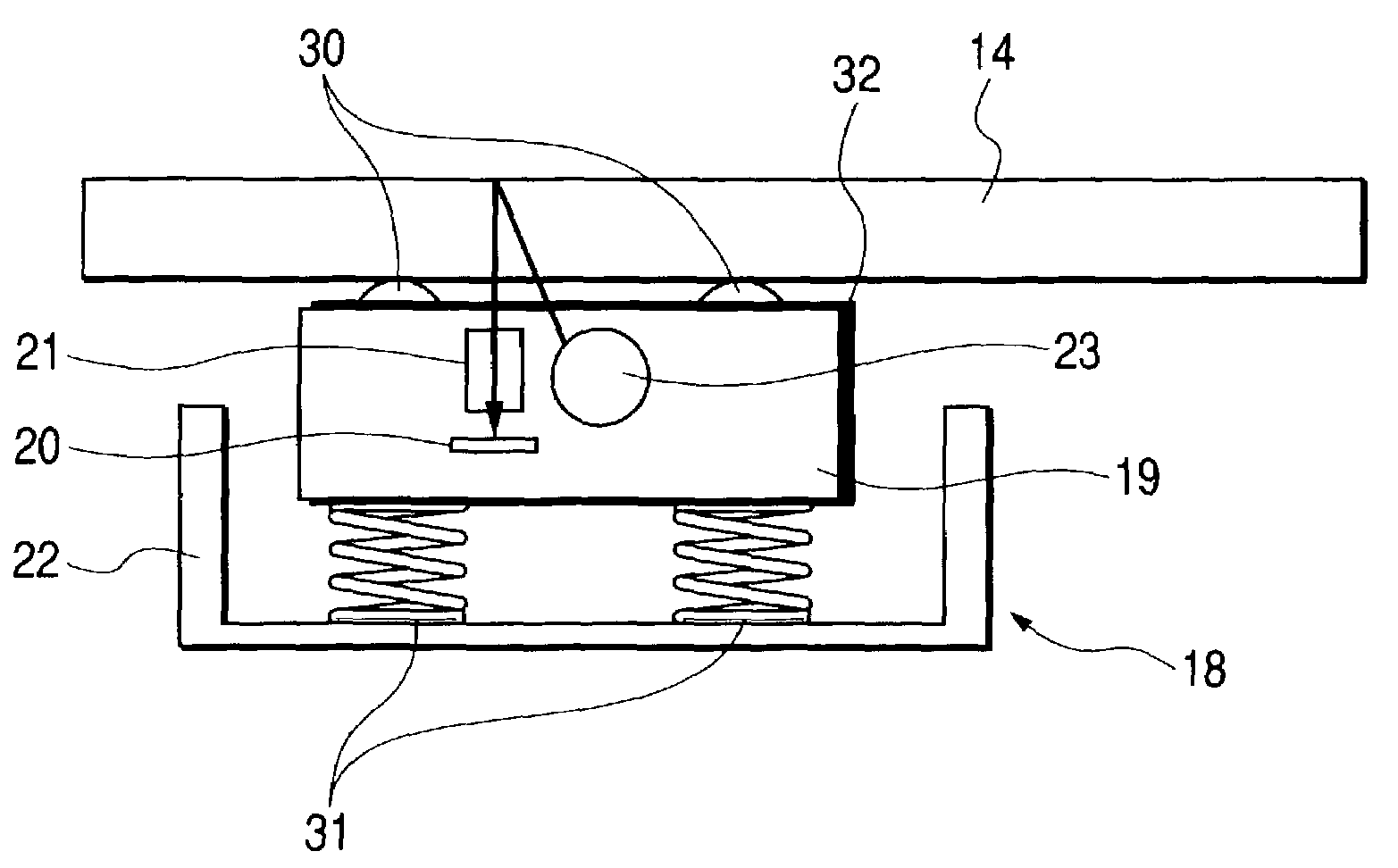
[0030]On the other hand, FIG. 2 shows an enlarged view of a configuration of the original reading unit 18. The original reading unit 18 is constructed of, as shown in FIG. 2, a metal frame body 22 and an image sensor unit 1...


PUM


Abstract

An image reading apparatus has a placing member where an original is placed, a reading unit for reading an image of the original in a way that moves relatively to the placing member, and a press member for pressing the reading unit against the placing member. The reading unit includes a conductive abutting portion coming into a contact with the placing member, and a grounding member for grounding the conductive abutting portion.

Description

BACKGROUND OF THE INVENTION[0001]1. Field of the Invention[0002]The present invention relates generally to an image reading apparatus for reading an image of the original, and more particularly to an image reading apparatus for reading in a way that brings a reading unit into a contact with a placing member on which the original is placed.[0003]2. Description of the Related Art[0004]Some of book-oriented image reading apparatuses utilized for, e.g., copying machines, image scanners etc. have hitherto used CCDs and contact image sensors as image sensors.[0005]In the case of using the image sensor, an optical system can be simplified and decreased in weight, and hence the whole apparatus can be downsized.[0006]This type of image sensor, however, has a such a problem that a focal depth is small, and the resolution declines due to a fluctuation of distance between a platen glass and the image sensor.[0007]In this respect, Japanese Patent Application Laid-Open No. 07-193689 copes with th...

Claims


Application Information

Patent Timeline
IPC IPC(8): H04N1/04H04N1/10H04N1/193
CPCH04N1/00976H04N1/1017H04N1/193H04N2201/0456
Inventor HANASHI, RYOSUGANUMA, TAKASHI
Owner CANON KK
Why Eureka
Try Eureka