Disk drive clock tracking circuit, error compensation circuit and method

a technology of error compensation and disk drive, applied in the field of clock tracking circuit, can solve the problems of increasing manufacturing throughput time, phase-in error of propagated servo-patterns, jitter in any clock recovered from the track, etc., and achieve the effect of improving the quality of position error signals and tracking

Inactive Publication Date: 2009-03-10
AGENCY FOR SCI SCI TECH & RES
View PDF11 Cites 6 Cited by
  • Summary
  • Abstract
  • Description
  • Claims
  • Application Information

AI Technical Summary

Benefits of technology

[0008]This invention proposes a method which can compensate the clock track closure without need for repetitive writing of the clock track. The method may also be used to compensate for written-in jitter of the clock track, hence significantly improving the quality of the position error signal and tracking.

Problems solved by technology

Such a clock track is said not to be “closed”, and causes jitter in any clock recovered from the track.
This may be time-consuming and increases manufacturing throughput time.
Written-in jitter results in phase-in error of propagated servo-patterns.
This in turn affects the quality (linearity) of the position error signal.
This will result in repeatable jitter of the read-back clock signal on the produced disks.

Method used


Image

  • Disk drive clock tracking circuit, error compensation circuit and method
  • Disk drive clock tracking circuit, error compensation circuit and method
  • Disk drive clock tracking circuit, error compensation circuit and method

Examples


Embodiment Construction

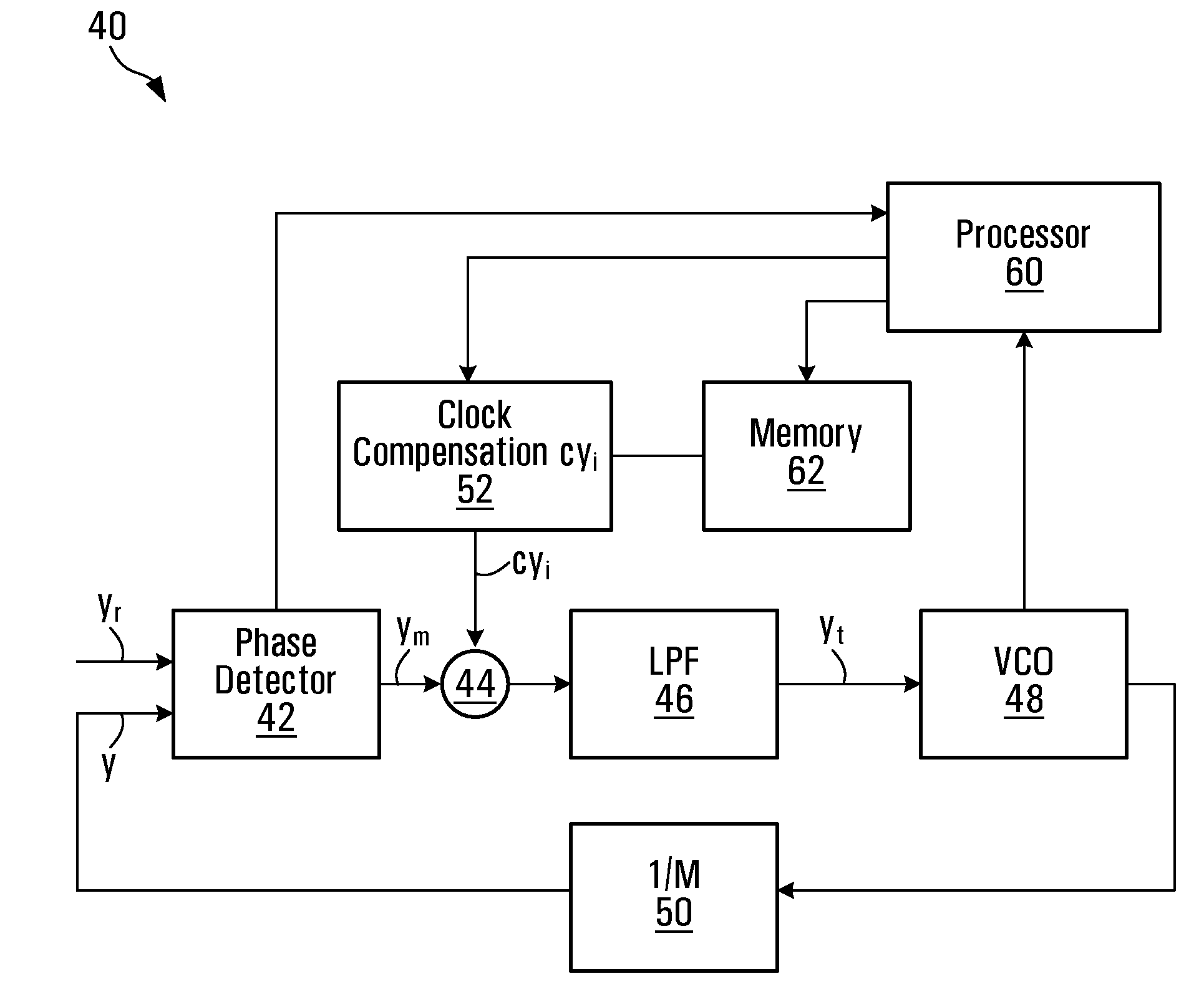
[0029]FIG. 1 schematically illustrates a disk surface 10, including a clock track 12. Clock track 12, has coded therein timing marks 14, used to generate a reference clock signal having a frequency fc. Timing marks 14 are written at periodic intervals of 1 / fc, and are thus evenly spaced.

[0030]The number of timing marks N written on track 12 in one revolution is

N=Tsfc  (1)

where Ts is the period of spindle motor rotation and fc is the frequency of the reference clock signal used to write the clock track.

[0031]The nominal distance di between two adjacent timing marks ti and ti-1 is

di=ωi / fc  (2)

where ωi is the angular rotating speed while writing the corresponding timing mark ti. If tN-1 is the last timing mark and t0 is the first timing mark then the angular distance between these two marks represents the clock closure dN, and is given by

[0032]dN=2⁢π-∑i=1N-1⁢di(3)

[0033]If the period of rotation is not an integer multiple of the nominal interval between two clock signals, the angular di...


PUM

PropertyMeasurementUnit
distanceaaaaaaaaaa
frequencyaaaaaaaaaa
phaseaaaaaaaaaa

Abstract

A clock tracking circuit and method uses a clock compensation signal to compensate for timing marks on a media disk. The clock compensation signal may compensate for at least one of improper clock track closure and written-in jitter of the timing marks used to produce the measured clock signal. The clock compensation signal may be used to control a controllable oscillator used to generate the clock signal that thereby provides a compensated clock signal.

Description

CROSS-REFERENCE TO RELATED APPLICATIONS[0001]This application claims benefits from U.S. Provisional Patent Application No. 60 / 667,081 filed Apr. 1, 2005, the contents of which are hereby incorporated herein by reference.FIELD OF THE INVENTION[0002]The present invention relates generally to computer devices, and more particularly to a clock tracking circuit for use in a disk drive servo controller and related methods.BACKGROUND OF THE INVENTION[0003]Data on modern computer disks is stored along circular tracks that are written and read by servo controlled, magnetic read / write heads. In order to allow for precise guidance of the read / write heads, disks are further coded with guide tracks. Typically, such guide tracks encode clock signals at defined intervals, and are placed on the disk surface during the manufacturing process. In order to allow for uniform guidance, clock signals are evenly spaced in the clock track. Even spacing can be assured by producing a clock signal at controlle...

Claims


Application Information

Patent Timeline
Patent Type & Authority Patents(United States)
IPC IPC(8): G11B5/09
CPCG11B5/59616G11B5/59638G11B5/59655G11B20/10222G11B20/10425G11B20/14G11B20/225
Inventor ZHANG, JINGLIANGHREDZAK, BRANISLAVLI, QINGGUO, GUOXIAO
Owner AGENCY FOR SCI SCI TECH & RES
Why Eureka
Try Eureka