Constant contact side bearing assembly

a side bearing and constant contact technology, applied in the direction of bogies, railway components, underframes, etc., can solve the problems of increasing the potential for derailment, limited speed derailment of the railway vehicle, so as to achieve the effect of minimal affecting flexibility, minimal affecting flexibility, and reducing the risk of derailmen

Inactive Publication Date: 2009-03-17
BASF CORP
View PDF27 Cites 2 Cited by
  • Summary
  • Abstract
  • Description
  • Claims
  • Application Information

AI Technical Summary

Benefits of technology

[0011]Accordingly, because the insulator is formed of microcellular polyurethane, the flexibility of the insulator is minimally affected by relatively cold temperatures, such as temperatures between −40° C. and 0° C. Because flexibility is minimally affected, the ability to dampen lateral pivoting of the car body relative to the bolster is also minimally affected and the maximum speed of the railway vehicle is minimally affected by the relatively cold temperatures. In addition, the insulator formed of microcellular polyurethane exhibits more compression travel than do current insulators formed of different materials. The increased compression travel enables the railway vehicle to travel at a higher speed while maintaining the cap in constant contact with the car body to avoid derailment.

Problems solved by technology

If contact between the car body and the side bearing is interrupted, the car body may slide relative to the bolster, which increases the potential for derailment.
At high speeds, forces generated by the oscillation of the truck and forces generated by the car body laterally pivoting relative to the truck can cause the wheels to climb off the track resulting in derailment of the railway vehicle.
Therefore, the speed of the railway vehicle is limited by the ability of the side bearing assembly to dampen the pivoting of the car body relative to the bolster.
Accordingly, cold temperatures decrease the ability of the insulator, such as the insulator in the '691 patent, to dampen the lateral pivoting of the car body relative to the truck.
Because the speed of the railway vehicle is limited by the dampening capability of the side bearing assembly, when the dampening capability is decreased at relatively cold temperatures, the speed of the railway vehicle must also be decreased.
If the compression travel is insufficient such that the insulator does not exert sufficient force on the cap, then the contact between the cap and the car body is interrupted, which can lead to movement of the car body relative to the bolster and increase the potential of derailment.
Because increased speed of the railway vehicle increases the pivoting of the car body relative to the bolster, the speed of the railway vehicle is limited by the compression travel of the insulator.
Current insulators are too rigid and too incompressible such that the compression travel of the insulators is insufficient to maintain constant contact at higher speeds.

Method used


Image

  • Constant contact side bearing assembly
  • Constant contact side bearing assembly
  • Constant contact side bearing assembly

Examples


second embodiment

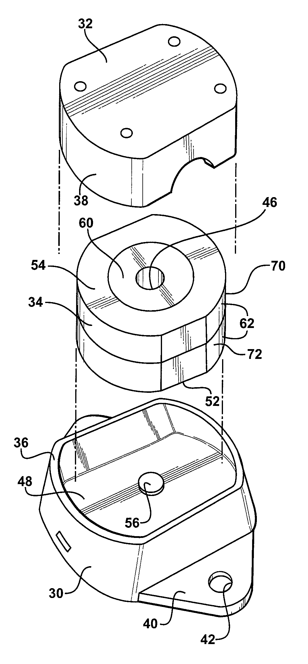
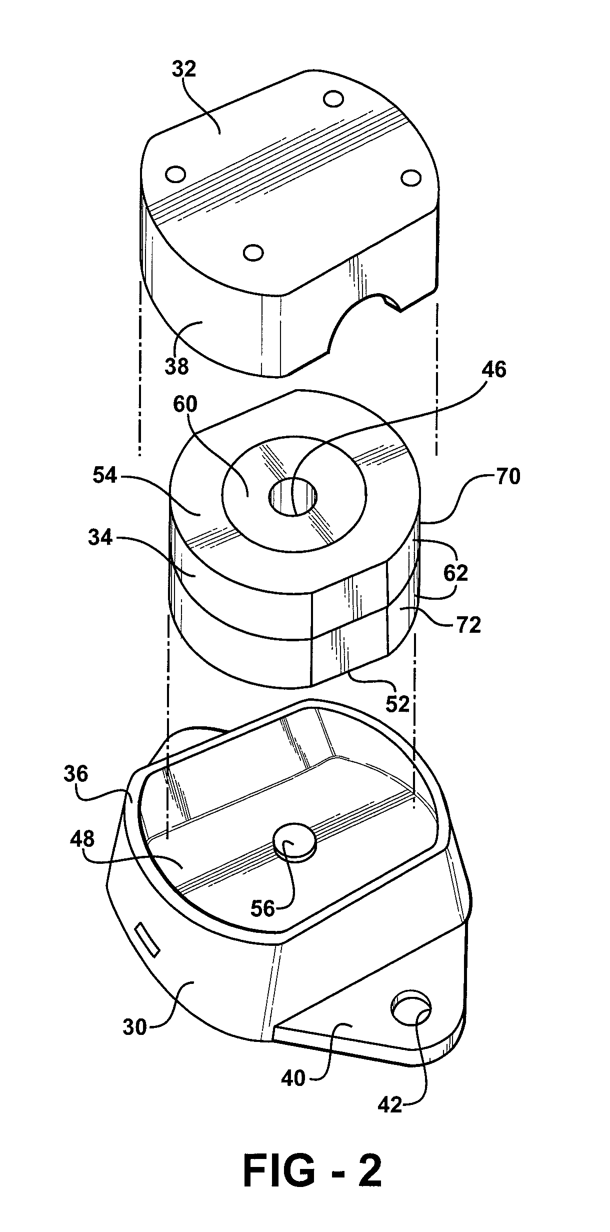
[0043]In the first and second embodiment, both the interior member 60 and the exterior member 62 present the bottom surface 52 for disposition adjacent the cage 30 and the top surface 54 for disposition adjacent the cap 32. The interior member 60 presents an outer surface 68 extending along the axis A between the bottom surface 52 and the top surface 54 of the insulator 34 and corresponding in shape to the inner surface 64 of the exterior member 62. As shown in FIGS. 5-6, the outer surface 68 of the interior member 60 is cylindrical and the inner surface 64 of the exterior member 62 is cylindrical. It should be appreciated that the outer surface 68 of the interior member 60 and the inner surface 64 of the exterior member 62 are not limited to being cylindrical but may be any shape such that the outer surface 68 corresponds in shape to the inner surface 64.

[0044]In the first and second embodiment, the interior member 60 abuts the inner surface 64 of the exterior member 62 for maintai...

first embodiment

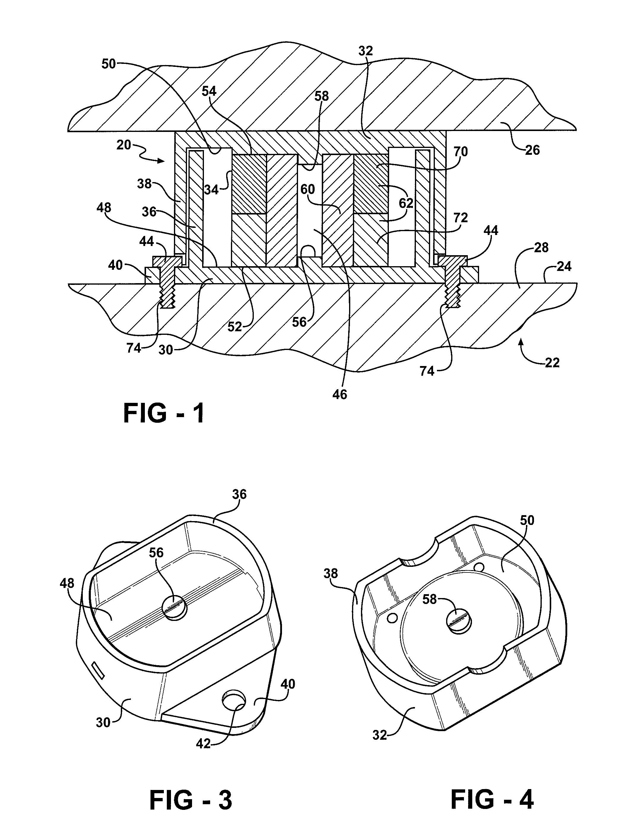
[0045]As shown in FIGS. 1-2 and 5, in the insulator 34, the exterior member 62 includes a first section 70 extending along the axis A and a second section 72 extending along the axis A adjacent the first section 70. The first section 70 and the second section 72 abut each other and are optionally adhered to one another.

[0046]Depending upon manufacturing constraints, difficulties may arise in forming a relatively large insulator from MCU. These difficulties are addressed by the first embodiment by forming the insulator 34 from the interior member 60, the first section 70 of the exterior member 62, and the second section 72 of the exterior member 62. In other words, the interior member 60, the first section 70, and the second section 72, are formed more easily, in some circumstances, than a single continuous insulator 34.

[0047]In the first embodiment, both the interior member 60 and the exterior member 62 have a common density. Alternatively, the interior member 60 has a first density...


PUM


Abstract

A side bearing assembly for a railway vehicle includes a cage, a cap coupled to and moveable relative to the cage, and an insulator disposed between the cage and the cap. The railway vehicle includes a bolster extending laterally and a car body disposed on the bolster. The cage is attached to the bolster and the cap supports a portion of the car body such that the side bearing assembly is disposed between the bolster and the car body to dampen lateral pivoting of the car body relative to the bolster. The insulator is formed of microcellular polyurethane for resiliently deforming and storing energy during compressive movement between the car body and the bolster through a range of temperatures between −40° C. and 80 ° C. Microcellular polyurethane maintains flexibility at this temperature range such that the side bearing assembly maintains its ability to dampen lateral pivoting through this temperature range.

Description

BACKGROUND OF THE INVENTION[0001]1. Field of the Invention[0002]The present invention relates to a side bearing assembly for a vehicle. Specifically, the invention relates to a side bearing assembly including an insulator for storing energy when the insulator is subjected to compressive forces.[0003]2. Description of the Related Art[0004]Side bearing assemblies for railway vehicles are known in the art. Generally, railway vehicles include a truck, i.e., a wheel assembly, and a car body disposed on the truck. For example, the car body could be a tanker. The truck includes a plurality of bolsters extending transversely across the truck. Each bolster of the truck includes a center bowl and the car body includes a body center plate corresponding to each center bowl. One of a pair of side bearing assemblies is attached to the bolster on either side of the center bowl. Each center bowl pivotally receives the corresponding body center plate such that the car body is laterally pivotal relat...

Claims


Application Information

Patent Timeline
Patent Type & Authority Patents(United States)
IPC IPC(8): B61F3/00B61F1/00
CPCB61F5/142
Inventor MITCHELL, NATHANIEL L.HUPRIKAR, ANAND G.BELL, TERRENCE A.
Owner BASF CORP
Why Eureka
Try Eureka