Radar device with overlapping short and long range sensors

a technology of short and long range sensors and radars, applied in measurement devices, using reradiation, instruments, etc., can solve the problems of waste of processing capabilities of processors, high output requirements, and increased signal processing volume, and achieve efficient processing of receive signals

Inactive Publication Date: 2009-03-17
FUJITSU GENERAL LTD +1
View PDF17 Cites 37 Cited by
  • Summary
  • Abstract
  • Description
  • Claims
  • Application Information

AI Technical Summary

Benefits of technology

[0017]With the foregoing in view, it is an object of the present invention to provide a radar device having two sensors for a long range and short range, which can make received signal processing efficient in an area where two detection areas for long range and short range overlap.
[0021]The radar device of the present invention can make processing of the receive signals efficient by stopping the analysis of the receive signal in one of the sensor in the area where the two detection areas, for long range and for short range, overlap.

Problems solved by technology

In contrary, transmitting a radio wave which reaches a long distance in a wide angle and searching a detection range equivalent to that of a radar device having two sensors requires high output and is technically difficult, and also a large volume of information on unnecessary objects is detected, which increases the signal processing volume.
However, an overlap of the detection areas generated in this radar device having a long range sensor and short range sensor requires analysis of the receive signals by both sensors.
Analyzing the received signals from the two sensors in the overlapped range requires time and involves a waste of processing capabilities of the processor, which diminishes efficiency.
Furthermore, if it is performed an operation to determine which of the detection results by the two sensors is regarded as important, the processing capabilities of the processor even more wastes, which worsens efficiency.

Method used


Image

  • Radar device with overlapping short and long range sensors
  • Radar device with overlapping short and long range sensors
  • Radar device with overlapping short and long range sensors

Examples


first embodiment

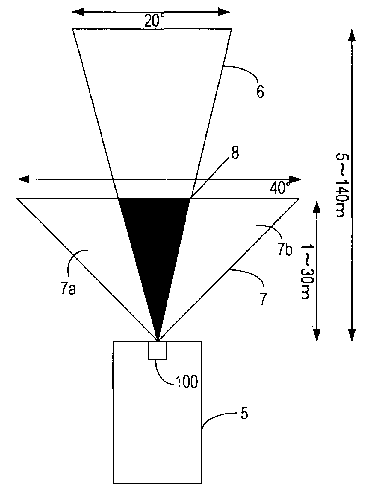
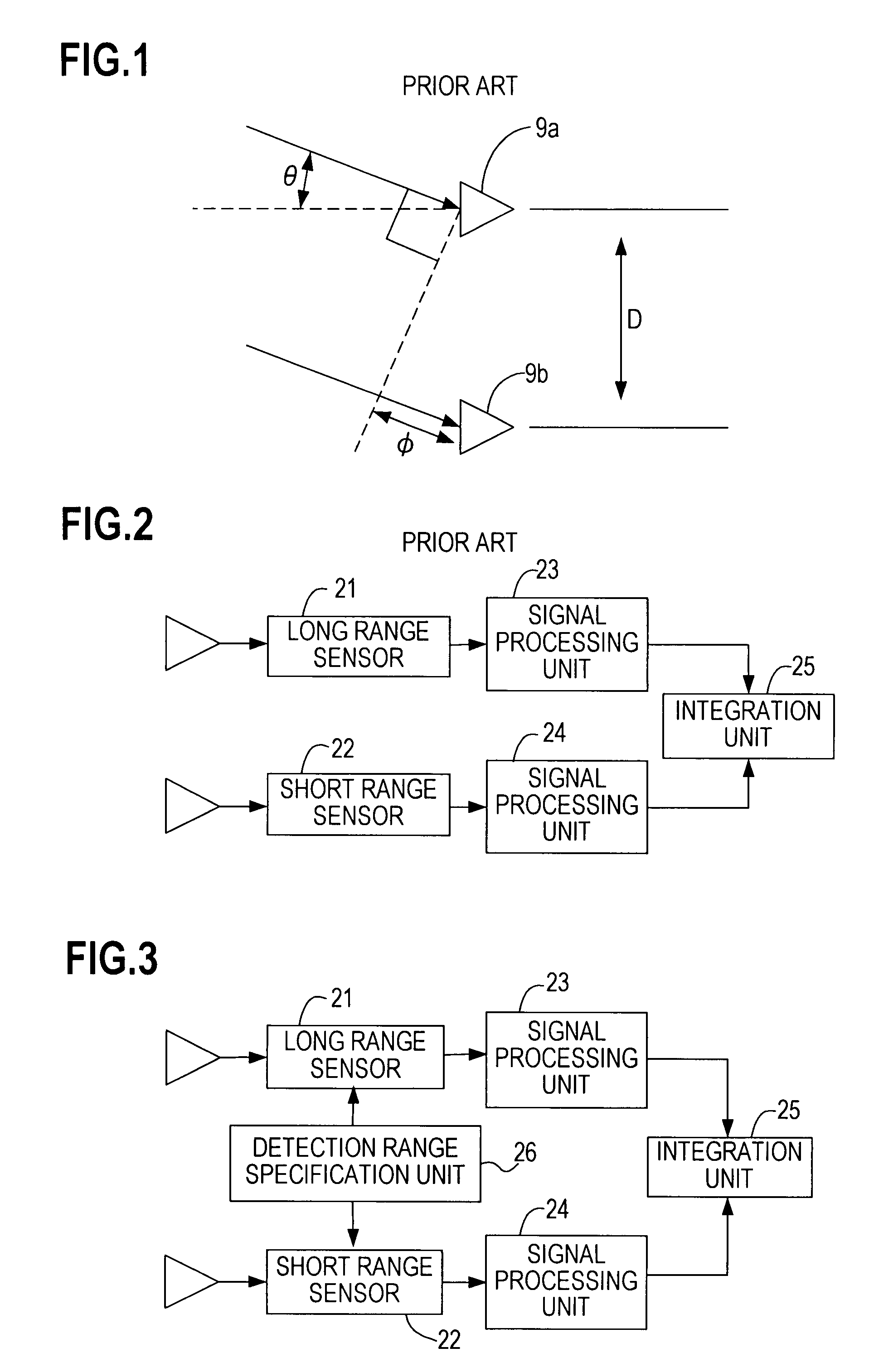
[0037]FIG. 3 is a conceptual diagram depicting overlap prevention of a radar device according to the present invention. A detection range specification unit 26 specifies a detection range for a long range sensor 21 and a short range sensor 22 respectively. At this time, specification is performed so that the respective detection ranges do not overlap. The long range sensor 21 and the short range sensor 22 send radio waves to the respective object detection ranges and detect objects. The long range sensor 21 and the short range sensor 22 supply received signals to signal processing units 23 and 24 respectively. The signal processing units 23 and 24 determine the distance, direction and velocity of the objects based on the supplied signals. The information on the objects determined by the signal processing units 23 and 24 is supplied to an integration unit 25, and the integration unit 25 integrates the provided information. Since there is no overlap in detection ranges, there is no ob...

second embodiment

[0070]FIG. 11 is a conceptual diagram depicting the overlap prevention in the radar device according to the present invention. A computing range specification unit 27 specifies the computing ranges of signal processing units 23 and 24 respectively. At this time, the specification is performed so that the computing ranges do not overlap. A long range sensor 21 and a short range sensor 22 send radio waves to the detection ranges of objects respectively to detect objects. The long range sensor 21 and the short range sensor 22 supply the received signals to the signal processing units 23 and 24 respectively.

[0071]Based on the supplied signals, the signal processing units 23 and 24 determine the distance, direction and velocity of the objects in the specified computing ranges. The information on the objects determined by the signal processing units 23 and 24 are supplied to an integration unit 25, and the integration unit 25 integrates the provided information. Since the computing ranges...

third embodiment

[0082]FIG. 13 is a conceptual diagram depicting the overlap prevention in the radar device according to the present invention. A primary radar specification unit 28 specifies the long range sensor 21 or the short range sensor 22 as a primary radar for using detection information in the overlapped range 8 to the integration unit 25. Then the long range sensor 21 and the short range sensor 22 transmit radio waves to the respective object detection ranges and detect objects. The long range sensor 21 and the short range sensor 22 supply the received signals to the signal processing units 23 and 24 respectively.

[0083]Then based on the supplied signals, the signal processing units 23 and 24 determine the distance, direction and velocity of the objects. The information on the objects determined by the signal processing units 23 and 24 are supplied to the integration unit 25, and the integration unit 25 integrates the provided information. At this time, the information from the sensor speci...


PUM


Abstract

A radar device has a long range radar sensor having a first transmission and receiving section for transmitting and receiving radio wave to a first detection range and a first signal processing section for detecting an object existing in the first detection range; a short range radar sensor having a second transmission and receiving section for transmitting and receiving a radio wave to a second detection range of which width is wider and of which distance is shorter than the first detection range and a second signal processing section for detecting an object existing in the second detection range; and a processing section for integrating information supplied from the first and second signal processing sections. And one of the long range radar sensor and the short range radar sensor stops a detection operation of the object to an overlapped range of both the detection ranges.

Description

CROSS-REFERENCE TO RELATED APPLICATIONS[0001]This application is based upon and claims the benefit of priority from the prior Japanese Patent Application No. 2006-217861, filed on Aug. 10, 2006, the entire contents of which are incorporated herein by reference.BACKGROUND OF THE INVENTION[0002]1. Field of the Invention[0003]The present invention relates to a radar device for detecting an object in front by radio waves, and more particularly to a radar device having two object detection sections.[0004]2. Description of the Related Art[0005]Radar devices installed on the front of a vehicle to measure distance to an object from the front of a vehicle and the relative velocity of the vehicle and the object have been proposed. By measuring the distance up to an object and the relative velocity, an alarm device for warning of an impending collision with an object in advance can be activated, or a brake can be activated to prevent collision with an object by using the measured distance and ...

Claims


Application Information

Patent Timeline
Patent Type & Authority Patents(United States)
IPC IPC(8): G01S13/93G01S13/931
CPCG01S13/34G01S13/87G01S13/931G01S7/03G01S2013/9375G01S2013/9353G01S2013/93271G01S2013/932
Inventor TSUCHIHASHI, MASATAKASHIMA, NOBUKAZUSHIRAKAWA, KAZUO
Owner FUJITSU GENERAL LTD
Why Eureka
Try Eureka