Liquid crystal display

a liquid crystal display and display quality technology, applied in the field of liquid crystal display devices, can solve the problems of narrow viewing angle, difficult to realize stable production of the device, and unsuitable mass production of rubbing, so as to reduce the viewing angle dependence of the liquid crystal domain, the effect of reducing the viewing angle dependence of the display quality

Inactive Publication Date: 2009-03-17
SHARP KK
View PDF18 Cites 11 Cited by
  • Summary
  • Abstract
  • Description
  • Claims
  • Application Information

AI Technical Summary

Benefits of technology

[0009]In order to overcome the problems described above, the present invention provide a liquid crystal display device having a wide viewing angle characteristic and superb display characteristics.

Problems solved by technology

However, conventional twisted nematic (TN) type and super twisted nematic (STN) type liquid crystal display devices have a problem of narrow viewing angle.
This arises a problem that it is difficult to realize stable production of the device.
However, rubbing is not suitable for mass-production because when a vertical alignment film is subjected to rubbing, rubbing streaks are likely to appear in the displayed image.

Method used


Image

  • Liquid crystal display
  • Liquid crystal display
  • Liquid crystal display

Examples


Embodiment Construction

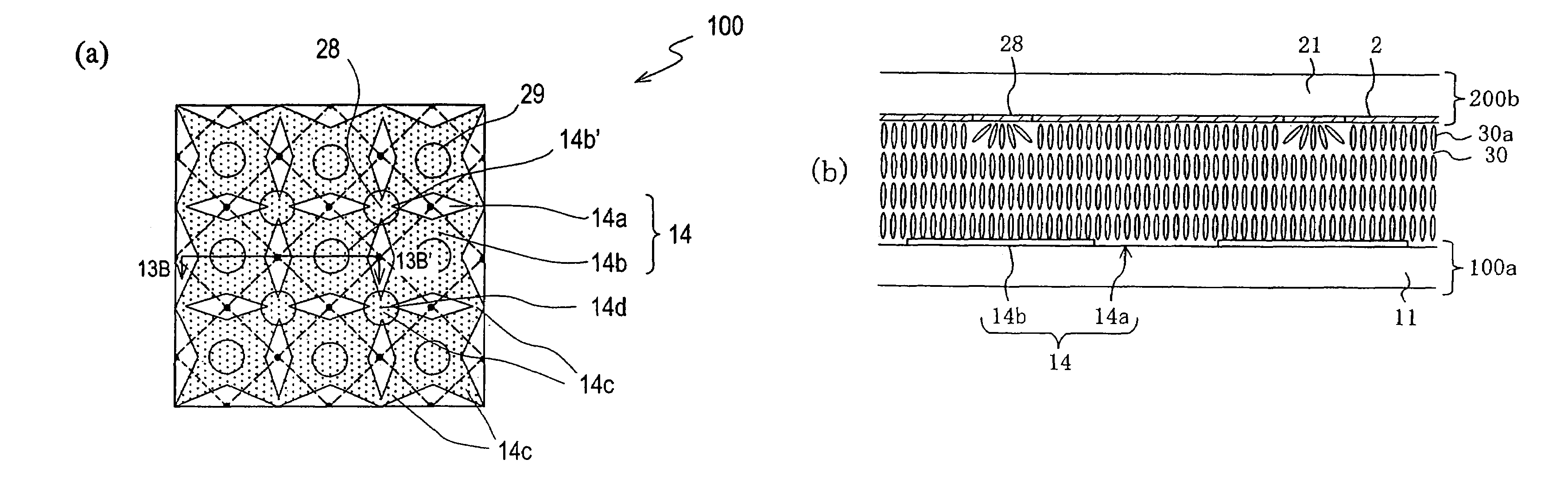
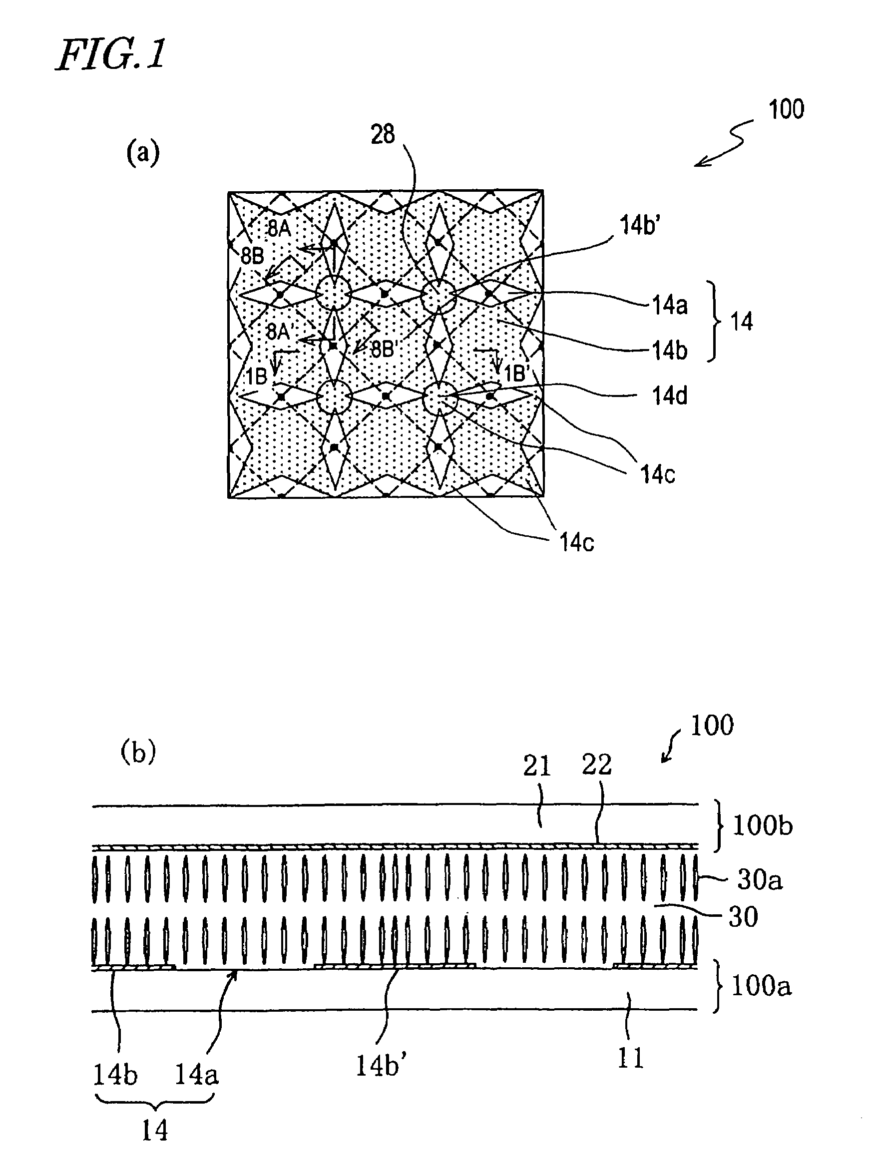
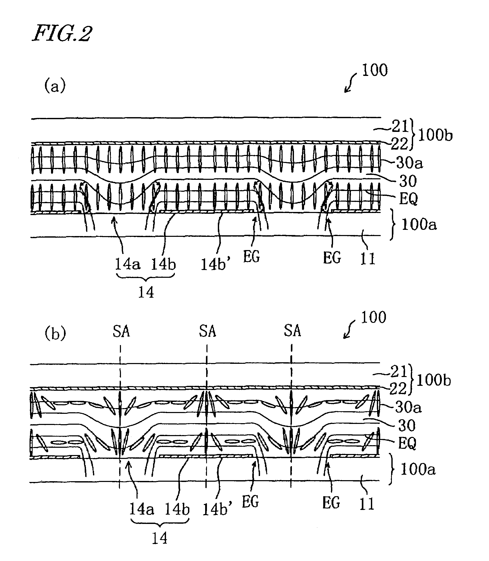
[0093]Hereinafter, embodiments of the present invention will be described with reference to the accompanying drawings.

[0094]First, an electrode structure of a liquid crystal display device according to the present invention and functions thereof will be described. A liquid crystal display device according to the present invention has superb display characteristics and is preferably used for an active matrix liquid crystal display device. The following embodiments of the present invention will be described regarding an active matrix liquid crystal display device using thin film transistors (TFTs), but the present invention is not limited thereto and is also applicable to an active matrix liquid crystal display device using MIM or a passive matrix liquid crystal display device. The following embodiments of the present invention will also be described regarding a transmission type liquid crystal display device, but the present invention is not limited thereto and is also applicable to ...


PUM

PropertyMeasurementUnit
voltageaaaaaaaaaa
voltageaaaaaaaaaa
angleaaaaaaaaaa

Abstract

A liquid crystal display device of the present invention comprises picture element regions each defined by a first electrode on a first substrate on the liquid crystal layer side and a second electrode provided on a second substrate and opposing the first electrode via the liquid crystal layer. In each picture element region, the first electrode includes openings and a solid portion; and the liquid crystal layer is in a vertical alignment with no voltage, and upon voltage application, forms liquid crystal domains each taking a radially-inclined orientation above the openings and the solid portion by an oblique electric field produced in edge portions of the openings. The solid portion of the first electrode includes unit solid portions and connecting portions each for connecting at least three unit solid portions to one another. The second substrate has a first orientation-regulating structure above each connecting portion for exerting an orientation-regulating force for placing liquid crystal molecules in the liquid crystal layer above the connecting portion into the radially-inclined orientation at least with voltage application.

Description

[0001]This application is the U.S. national phase of international application PCT / JP2004 / 008419 filed 9 Jun. 2004 which designated the U.S. and claims priority to JP 2003-166929 filed 11 Jun. 2003, the entire contents of each of which are hereby incorporated by reference.TECHNICAL FIELD[0002]The present invention relates to a liquid crystal display device, and more particularly to a liquid crystal display device having a wide viewing angle characteristic and providing a high quality display.BACKGROUND ART[0003]In recent years, thin and lightweight liquid crystal display devices have been used as personal computer displays and display sections of mobile information terminal devices. However, conventional twisted nematic (TN) type and super twisted nematic (STN) type liquid crystal display devices have a problem of narrow viewing angle. Various technical developments have been undertaken to solve the problem.[0004]A typical technique for improving the viewing angle characteristic of ...

Claims


Application Information

Patent Timeline
Patent Type & Authority Patents(United States)
IPC IPC(8): G02F1/1337G02F1/1333G02F1/1343
CPCG02F1/133707G02F1/133753G02F1/1337
Inventor KUBO, MASUMIYAMAMOTO, AKIHIROOCHI, TAKASHI
Owner SHARP KK
Why Eureka
Try Eureka