Switchplate area light

a switchplate area light and switch plate technology, applied in the direction of cathode-ray/electron beam tube circuit elements, fixed installations, lighting and heating apparatus, etc., can solve the problems of light needs, limited return paths, and increased manufacturing costs

Inactive Publication Date: 2009-03-24
NITE IZE INC
View PDF23 Cites 76 Cited by
  • Summary
  • Abstract
  • Description
  • Claims
  • Application Information

AI Technical Summary

Problems solved by technology

However, few provide a return path for current used to power a light through a load controlled by a switch.
Unfortunately, many times light is needed where no neutral wire is available.
In addition, the Cunningham invention requires a frame to house the LED assembly necessitating a significant protrusion from the wall as well as additional manufacturing cost.
In addition the device will only work with a conventional toggle.
Many light switches today are of the rocker type and Barton's invention would not work well with these.
In addition, according to Barton's FIG. 2A, the electronics and battery package appear to take a significant amount of room in the outlet box.
Elghoroury's design appears to cover an existing switchplate with a larger device and so cannot be used in areas where the existing switchplate is the largest size cover that will work in the available space.
As with previous patents cited, there is a power issue with the preferred embodiment of four LEDs.
(b) Having an excessive amount of light emanating from the LED has a detrimental effect on night vision.
(d) White LEDs are a relatively expensive component compared to the other electronic parts in the LED drive circuitry.
In addition, prior art also does not appear to have considered the problem of reactive loads.
These use an electronic ballast and so present a more reactive load to the LED driver circuitry.
The present invention offers a number of advantages over the prior art:
(a) The invention provides usable pathway lighting in areas where a conventional plug-in night light is unusable due to lack of an electrical socket.
(b) The LED is mounted on the outside of the switchplate and is oriented in such a way as to make full use of its light output without the use of any separate intervening optical elements such as reflectors, lenses or diffusers.
(c) The LED is deliberately driven below its rated input, resulting in extremely long life. The LED and associated circuitry should last the life of the structure in which it is installed. The light output is nonetheless sufficient for adequate nighttime pathway lighting.
(d) Because the current draw is low, multiple devices may be connected to the same electrical circuit controlling the same load. This is typically the case with 3-way and 4-way switch installations.
(e) Because the LED and associated electronics are built onto the switchplate, no light is necessary on the rocker or toggle switch itself. The invention thus serves the dual purpose of providing useful area lighting and serving as a locator for the switch toggle or rocker.
(f) The majority of the light from the LED is directed away from the user and onto the floor thus helping to preserve night vision.
If the night light is not illuminated when the switch is off, there may be a problem with the load.

Method used


Image

  • Switchplate area light
  • Switchplate area light
  • Switchplate area light

Examples


Embodiment Construction

—FIGS. 1A, 1B, 1C, AND 3A-PREFERRED EMBODIMENT

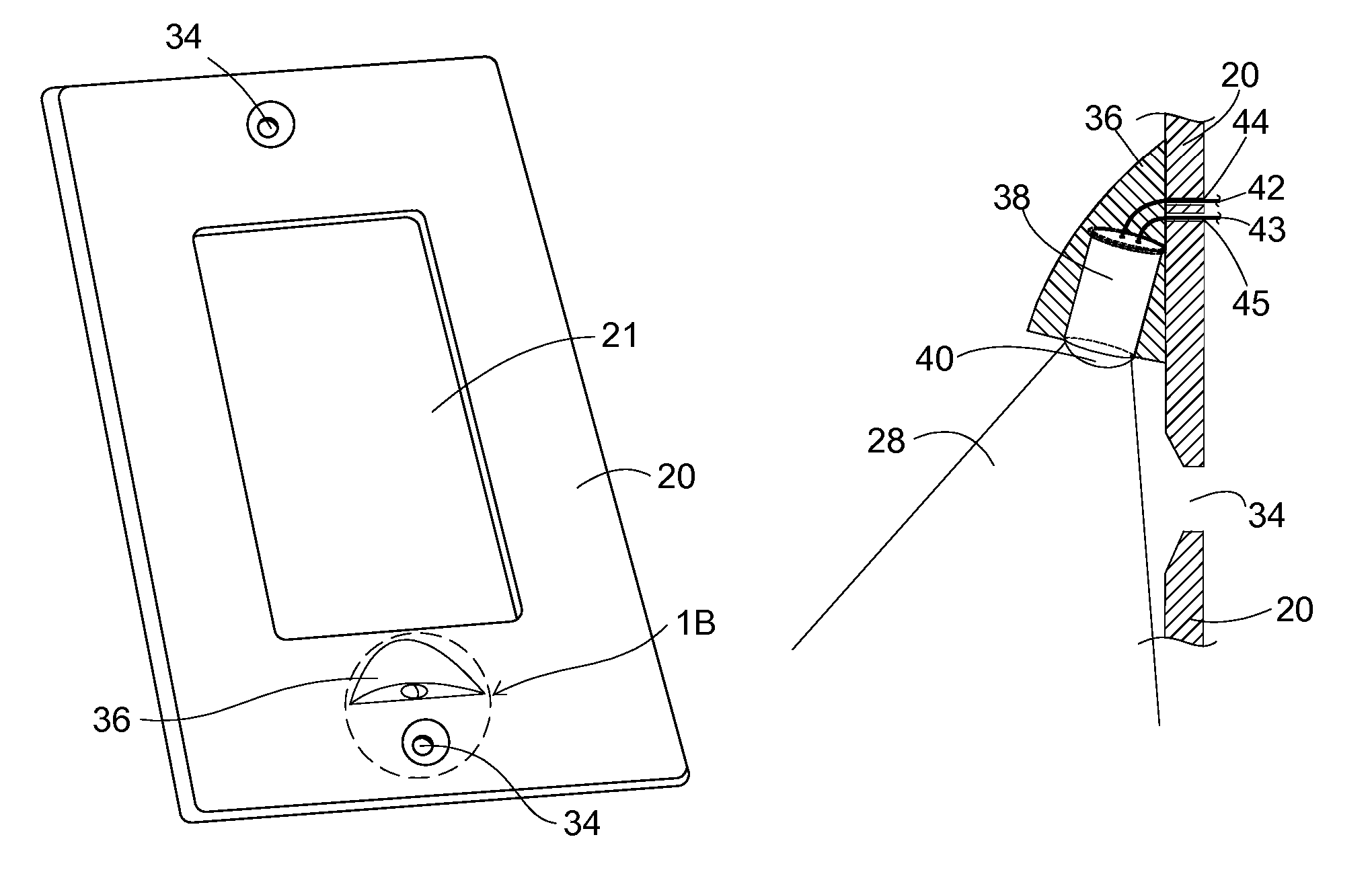
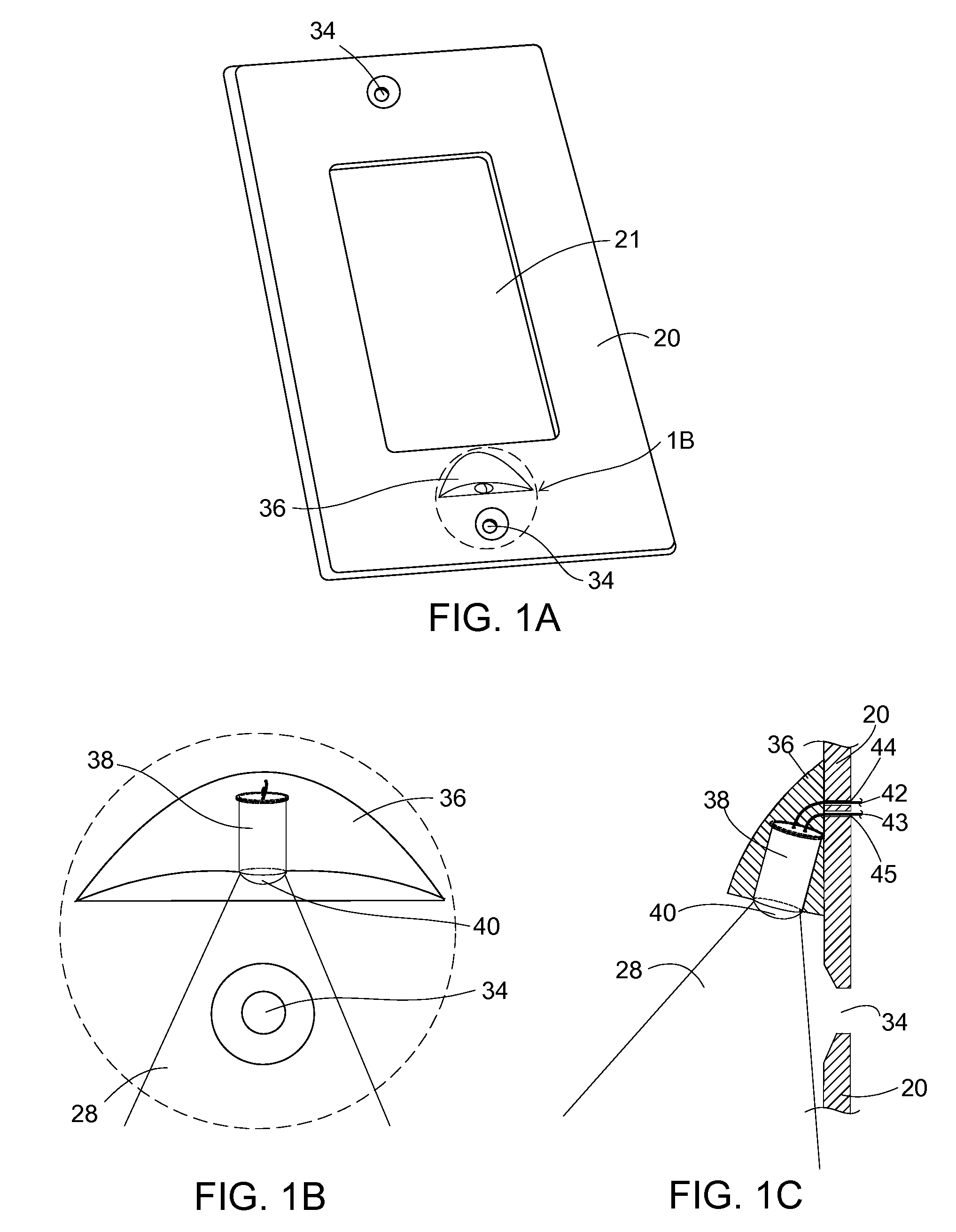
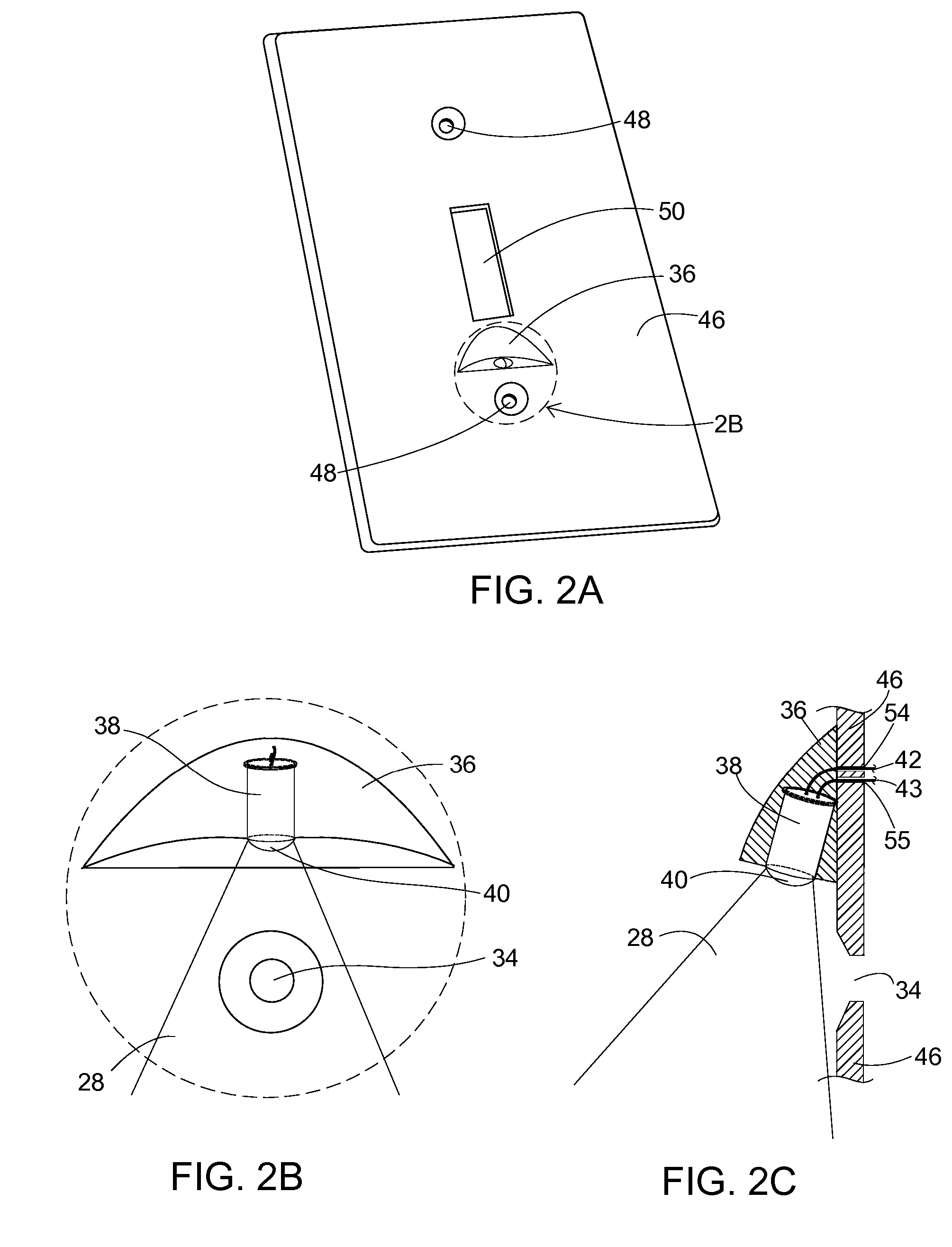
[0109]The preferred embodiment of the present invention is illustrated from the front in FIG. 1A and back in FIG. 3A. A cylindrical LED 38 is molded or fitted into a housing 36 on the structure of the switchplate 20 at such an angle that the light rays 28 emanating from the LED 38 provide illumination on the pathway below the switchplate. Other than the leads 42 and 43 exiting the LED 38 which protrude though holes 44 and 45 in the switchplate 20, the LED 38 is mounted entirely on the front of the switchplate 20. The housing 36 surrounding the LED 38 is of such a composition that it allows some light to escape. Alternatively, the switchplate 20 itself may be modified to provide an enclosure for the LED 38 that angles it away from the plane of the switchplate in the same manner as with a separate housing 36. The built-in lens 40 molded into the end of the LED 38 protrudes from the housing 36 and is not covered by the housing.

[0110]The LED...


PUM


Abstract

A light emitting diode (LED) and associated driver circuit wherein the LED is mounted on the front of a switchplate and the driver circuit on the back of the switchplate. The LED is mounted at a downward angle on the outside of the switchplate so as to light a pathway beneath the switchplate. The drive electronics are designed to work with a return path through an electrical load. Additionally, the LED driver circuit is designed to allow operation of the LED with both resistive and reactive loads controlled by the switch to which the switchplate is connected. The device is also designed to be connected to any electrically valid combination of 2-way, 3-way, and 4-way switches either singly or in combination.

Description

CROSS-REFERENCE TO RELATED APPLICATIONS[0001]This application claims the benefit of provisional patent application Ser. No. 60 / 760,626 filed 2006 Jan. 21 by the present inventor.FEDERALLY SPONSORED RESEARCH[0002]Not ApplicableSEQUENCE LISTING OR PROGRAM[0003]Not ApplicableBACKGROUND OF THE INVENTION[0004]1. Field of Invention[0005]This invention relates to alternating current powered night lights, specifically to such night lights where the load controlled by a switch or switches is used as the electrical return path.[0006]2. Prior Art[0007]There are many night lights on the market in this crowded field of art. However, few provide a return path for current used to power a light through a load controlled by a switch. Most current night lights plug into an existing outlet receptacle and light a small area with a low level of light. U.S. Pat. No. 6,561,677 (2003) by Leen is one example. Others are wired into an outlet box. U.S. Pat. No. 6,547,411 B1 (2003) by Dornbusch is typical of s...

Claims


Application Information

Patent Timeline
Patent Type & Authority Patents(United States)
IPC IPC(8): F21V33/00
CPCF21S8/035H05B33/0803H05B33/0809H05B33/0812H01H9/18Y02B20/343H05B45/395Y02B20/30Y10S362/80
Inventor GLAZNER, GREGORY F
Owner NITE IZE INC
Why Eureka
Try Eureka