Fluorescent lamp luminaire

a fluorescent lamp and luminaire technology, applied in lighting applications, lighting sources, lighting and heating apparatuses, etc., can solve the problems of degrading the performance of other ballasts and lamps, affecting the efficiency of luminaires, etc., and achieves the effect of wide spacing to mounting height ratio, easy installation, and high luminaire efficiency

Inactive Publication Date: 2009-03-24
GENLYTE THOMAS GRP LLC
View PDF64 Cites 18 Cited by
  • Summary
  • Abstract
  • Description
  • Claims
  • Application Information

AI Technical Summary

Benefits of technology

[0015]The present invention provides a luminaire utilizing multiple long twin tube compact fluorescent lamps (i.e. Philips PL-L lamps) that serves as a low-bay or optionally hi-bay luminaire while maintaining high luminaire efficiency. The luminaire of the p

Problems solved by technology

Electronic ballast and lamps are sensitive to heat and thus degrade the performance unless properly positioning and venting is established.
The

Method used


Image

  • Fluorescent lamp luminaire
  • Fluorescent lamp luminaire
  • Fluorescent lamp luminaire

Examples


Embodiment Construction

[0031]The following describes a fluorescent luminaire, numerous specific details and alternative configurations are set forth in order to provide an understanding of the present invention. It should be appreciated that such descriptions are merely for convenience and that such are selected solely for the purpose of illustrating the invention. Other and different fluorescent luminaires may utilize the inventive features described herein. Hence, reference to the figures showing several embodiments of the present invention is made to describe the invention and not to limit the scope of the disclosure and claims herein.

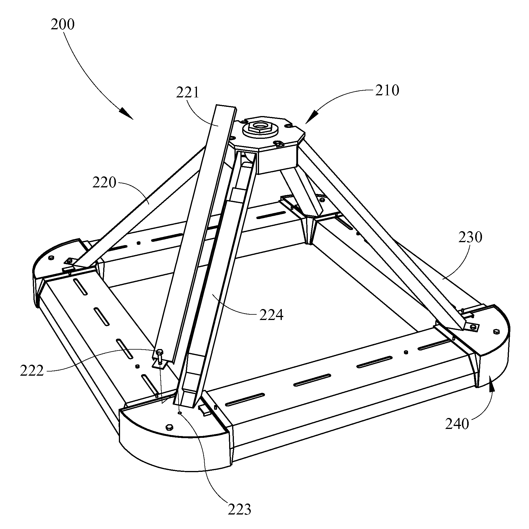
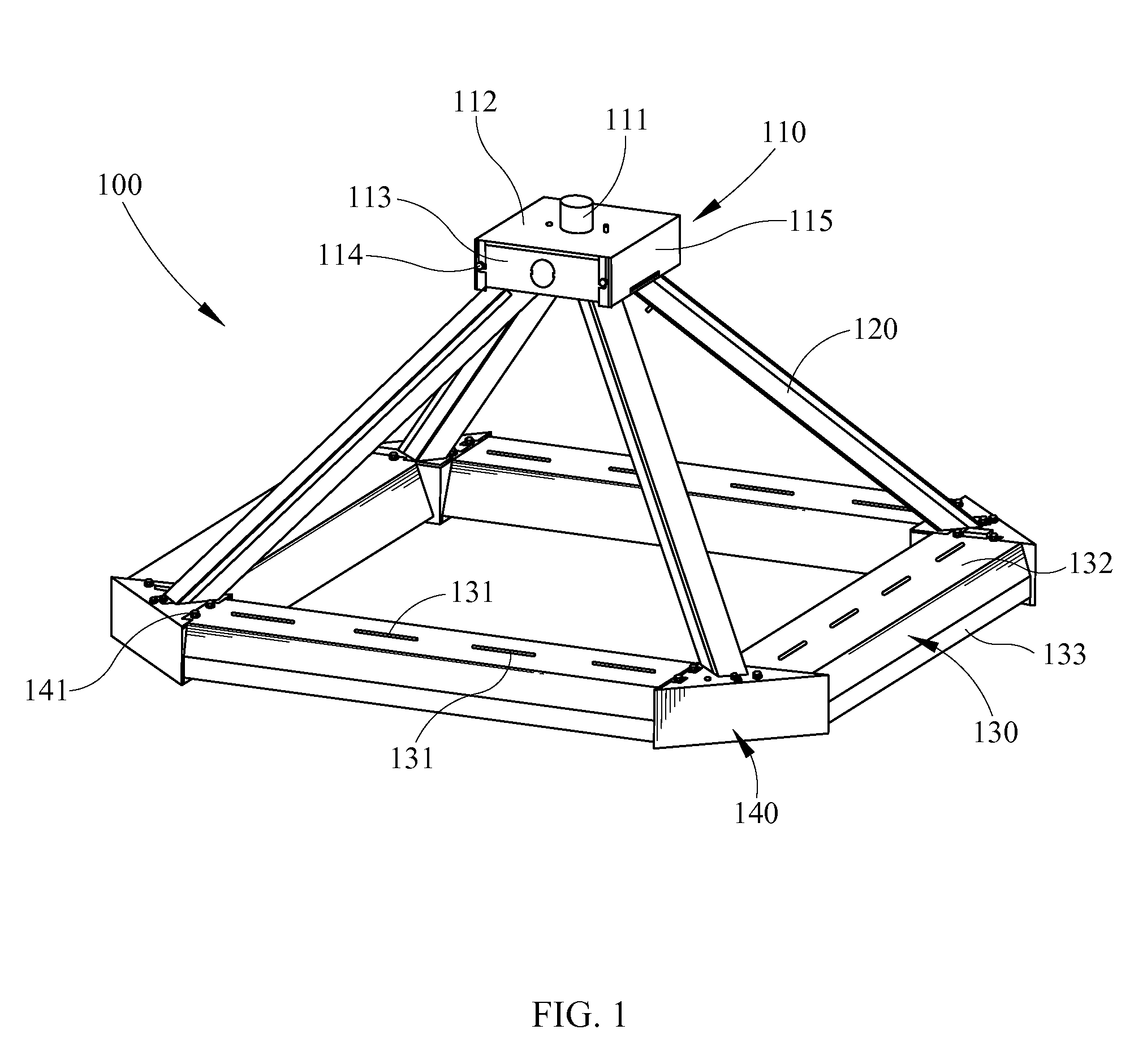
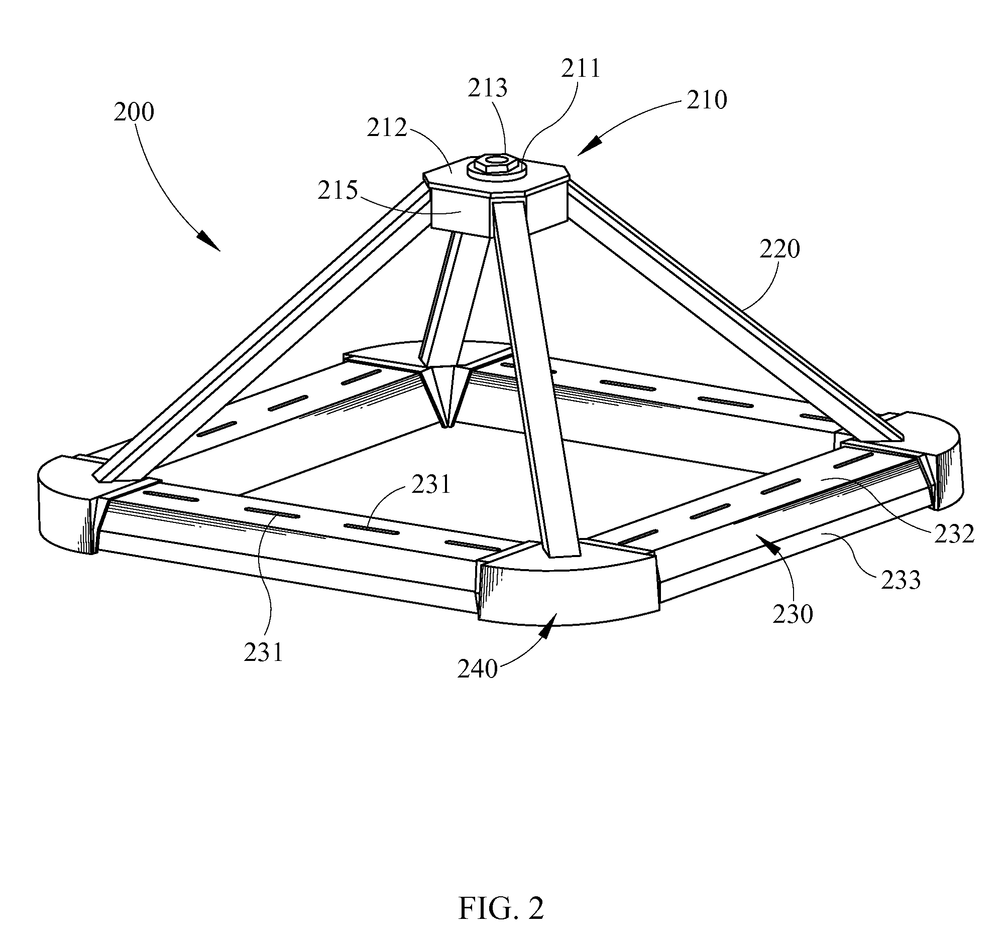
[0032]Referring to FIG. 1, showing an embodiment of the fluorescent lamp luminaire of the present invention, the instant invention is described. Shown here is luminaire 100 having four channel reflectors 130 arranged in a substantially planar square pattern forming a light emitting region. Channel reflectors 130 have a top wall 132 and a pair of opposing downwardly depend...


PUM


Abstract

The luminaire of the present invention comprises at least two channel reflectors geometrically arranged in substantially a common plane forming a light emitting region, each channel reflector has one fluorescent lamp holder extending therein and each channel reflector has a channel reflector retaining arm having a ballast therein and extending to a luminaire supporting base.

Description

CROSS-REFERENCE TO RELATED APPLICATIONS[0001]This application claims benefit of and priority to U.S. Application Ser. No. 60 / 676,351, currently pending, filed on Apr. 29, 2005.BACKGROUND OF THE INVENTION[0002]1. Field of the Invention[0003]The present invention relates to a lighting luminaire which more efficiently produces lumens from a compact high intensity fluorescent lamp.[0004]2. Description of the Related Art[0005]The need for lighting large areas has led to the development of a variety of hi-bay and low-bay luminaries. The luminaries, hi-bay and low-bay, found their name in the construction of some types of industrial facilities where a skeletal framework is used to form an interior subspace called a “bay”. Yet, in the lighting industry, this term bay has expanded to encompass almost any large area to be lit. Typical applications of hi-bay and low-bay luminaries include street lighting, parking lot lighting, building flood lighting, sports arena lighting, industrial lighting...

Claims


Application Information

Patent Timeline
IPC IPC(8): F21S8/06
CPCF21S2/00F21S8/06F21V23/026F21V29/004F21W2131/10F21W2131/105F21W2131/407F21Y2103/00F21Y2103/025F21Y2113/00F21V29/83F21Y2103/37
Inventor WAYCASTER, WILLIAM BRADLEYCOLLINS, SCOTT
Owner GENLYTE THOMAS GRP LLC
Why Eureka
Try Eureka