Arc tube and method of manufacturing same

A manufacturing method and technology for light-emitting tubes, which are applied in the manufacture of discharge tubes/lamps, cold cathodes, electrode systems, etc., can solve the problems of unstable electrode position, shortened life, and increased gap between electrodes and thin tubes. Achieving the effect of color fluctuation, improved life characteristics, and reduced color fluctuation

Inactive Publication Date: 2012-07-04
NGK INSULATORS LTD
View PDF5 Cites 0 Cited by
  • Summary
  • Abstract
  • Description
  • Claims
  • Application Information

AI Technical Summary

Problems solved by technology

In addition, the positioning of the electrode is carried out by providing a rod-shaped or ring-shaped stopper on the electrode and making the stopper contact with the end of the ceramic tube (the end of each thin tube). Therefore, due to the The length of the capillary fluctuates, the protruding amount of the tip of the electrode to the inner surface of the light-emitting part fluctuates, and the distance from the inner surface of the light-emitting part fluctuates, which causes the color fluctuation of the lamp or the decrease in the life of the lamp
In addition, since each electrode is positioned by both ends of the ceramic tube, if the overall length of the ceramic tube fluctuates, it becomes the cause of fluctuations in the distance between the two electrodes, reduction in lamp efficiency, or fluctuation in color
In addition, since there is a gap between the capillary and the electrode lead, it is easy to shift when sealing, and the position of the electrode relative to the central axis of the arc tube is not fixed, causing color fluctuations
[0006] As described above, since the diameter of the tip of the electrode cannot be made larger than the inner diameter of the capillary tube, the temperature of the electrode tends to rise, causing a decrease in the life of the electrode.
On the other hand, if the inner diameter of the narrow tube is increased, the diameter of the electrode tip can be increased, but in this case, the gap between the electrode and the inner diameter of the thin tube increases.
As a result, the luminescent substance tends to remain in the gap, and corrosion of the portion where the electrode is sealed is likely to occur.
In addition, the amount of luminescent substance is unstable, and the position of the electrode relative to the central axis of the arc tube is not fixed, so it also becomes a cause of color fluctuation.
Therefore, when the diameter other than the tip portion of the electrode is increased in accordance with the inner diameter of the thin tube in order to reduce the gap, the thermal stress due to the difference in thermal expansion coefficient between the electrode and the thin tube increases and easily occurs in the thin tube. crack
In addition, since the heat capacity of the electrodes increases, there is a problem that the lamp efficiency decreases

Method used


Image

  • Arc tube and method of manufacturing same
  • Arc tube and method of manufacturing same
  • Arc tube and method of manufacturing same

Examples


no. 1 Embodiment

[0143] The state of occurrence of cracks and the amount of leakage of the light-emitting part of the light-emitting tubes produced by the manufacturing methods of Examples 1 and 2 and Comparative Example 1 were measured. Furthermore, fluctuations in the position of the tip of the first electrode (fluctuation in the distance from the ceramic wall surface to the position of the tip of the first electrode) were confirmed.

Embodiment 1

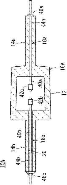
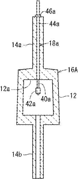
[0145] according to image 3 The first fabrication method shown produces a figure 1 10 light emitting tubes are shown (the first light emitting tube 10A). In this case, the inner diameter of the first narrow tube 14a of the first ceramic tube 16A was 0.5 mm, and the inner diameter of the second thin tube 12b was 0.8 mm. First, prepare the first ceramic molded body 22a and the second ceramic molded body 22b as follows (refer to Figure 4A as well as Figure 4B ) forming slurry. That is, 100 parts by weight of alumina powder and 0.025 parts by weight of magnesium oxide were mixed as a raw material powder, 30 parts by weight of polybasic acid ester was mixed as a dispersion medium, 4 parts by weight of MDI resin was mixed as a gelling agent, and 2 parts by weight of a dispersant was mixed. As a catalyst, 0.2 parts by weight of triethylamine was mixed to form a molding slurry.

[0146] After pouring the molding slurry into the first casting mold and the second casting mold ma...

Embodiment 2

[0150] according to Figure 7 The second fabrication method shown produces a Figure 5 Ten sintered bodies are shown (second ceramic tube 16B). In this case, too, the inner diameter of the first narrow tube 14a is made smaller than the inner diameter of the second thin tube 14b.

[0151] First, ten first ceramic molded bodies 22a and second ceramic molded bodies 22b were produced in the same manner as in Example 1 above (see Figure 4A as well as Figure 4B ).

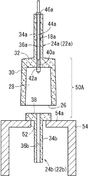
[0152] Thereafter, the first ceramic molded body 22a produced as described above was calcined at a temperature of 1200°C in the atmosphere to produce the first ceramic calcined body 24a, and the second ceramic molded body 22b was fired at a temperature of 1000°C in the atmosphere. The second ceramic calcined body 24b is produced by performing calcining at 0°C. Thereafter, use Figure 6A The jig 54 sequentially assembles the first ceramic pre-fired body 24a, the first electrode 18a and the second ceramic pre-fired...


PUM

PropertyMeasurementUnit
diameteraaaaaaaaaa
diameteraaaaaaaaaa
diameteraaaaaaaaaa

Abstract

The invention provides an arc tube which simplifies the manufacturing process, reduces the color fluctuation, prolongs the service lifetime, and improves the light efficiency and reliability. The first arc tube (10A) is provided with a ceramic tube (16A) which includes a light emitting body (12) for light therein, a first capillary (14a) and a second capillary (14b) integral with respective opposite sides of the light emitting body (12). A first electrode (18a) is inserted and sealed in the first capillary (14a), and a second electrode (18b) is inserted and sealed in the second capillary (14b). The first electrode (18a) is sealed in the first capillary (14a) by shrink fitting.

Description

technical field [0001] The present invention relates to a light-emitting tube for a high-intensity discharge lamp such as a high-pressure sodium vapor lamp or a metal halide lamp, and a method for manufacturing the same. The first thin tube and the ceramic tube of the second thin tube are formed, the first electrode is inserted and sealed in the first thin tube of the ceramic tube, and the second electrode is inserted and sealed in the second thin tube. Light-emitting tube and its manufacturing method. Background technique [0002] In a ceramic metal halide lamp, a pair of electrodes inserted into a ceramic tube for a high-intensity discharge lamp ionizes a metal halide to obtain discharge emission. [0003] Such a ceramic tube has a pair of thin tubes formed by determining the axial positions facing the light-emitting part, respectively. Electrode insertion holes are respectively provided in the thin tubes, and electrodes are inserted through these electrode insertion hol...

Claims


Application Information

Patent Timeline
Patent Type & Authority Applications(China)
IPC IPC(8): H01J61/30H01J9/04
CPCH01J9/266H01J9/32H01J9/323H01J61/366Y10T29/49117
Inventor 宫泽杉夫渡边敬一郎大桥玄章
Owner NGK INSULATORS LTD
Why Eureka
Try Eureka