Atomizer for electronic cigarette and electronic cigarette

An atomizer and electronic cigarette technology, applied in the field of electronic cigarettes, can solve the problems of high cost, many parts, complex assembly process, etc., and achieve the effects of low cost, simple structure and simple assembly process

Active Publication Date: 2013-02-13
SHENZHEN FIRST UNION TECH CO LTD
View PDF8 Cites 59 Cited by
  • Summary
  • Abstract
  • Description
  • Claims
  • Application Information

AI Technical Summary

Problems solved by technology

[0003] Depend on figure 1 In the prior art shown in , the structure of the atomizer for electronic cigarette is complex, it contains many parts, the assembly process is complicated, and the cost is high

Method used


Image

  • Atomizer for electronic cigarette and electronic cigarette
  • Atomizer for electronic cigarette and electronic cigarette
  • Atomizer for electronic cigarette and electronic cigarette

Examples


specific Embodiment 1

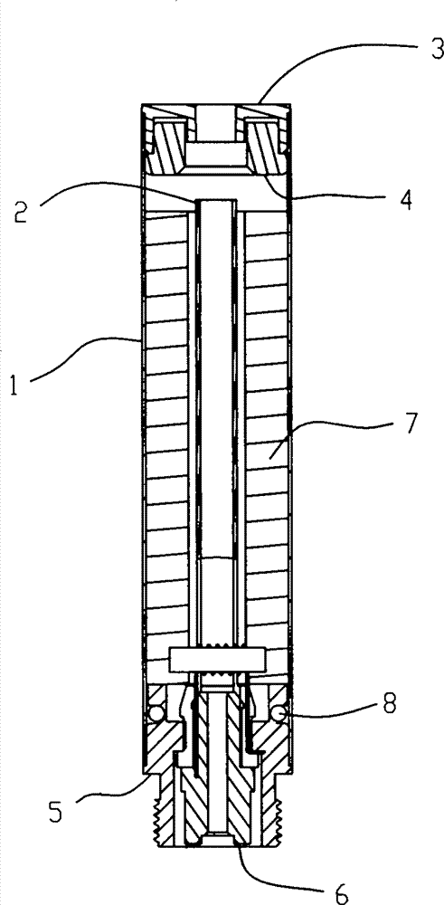
[0040] Such as figure 2As shown, an atomizer for electronic cigarettes includes an atomizing sleeve 1, a nozzle cover 3, a threaded sleeve 5, an electrode ring 6 fixedly arranged in the threaded sleeve 5, and an electrode ring 6 arranged in the atomizing sleeve 1. The oil storage substance and the heating wire assembly 10, an insulating ring 11 is arranged between the threaded sleeve 5 and the electrode ring 6, and the suction nozzle cover 3 and the threaded sleeve 5 are respectively tightly fitted on the two ends of the atomizing sleeve 1 , the two pins of the heating wire assembly 10 are respectively connected to the threaded sleeve 5 and the electrode ring 6; the oil storage substance is composed of at least two layers with different densities; the atomizer does not include glass fiber Tube 2.

[0041] An air flow channel is provided in the oil storage substance, and the heating wire assembly 10 is located in the channel. During operation, the heating wire assembly 10 ab...

specific Embodiment 2

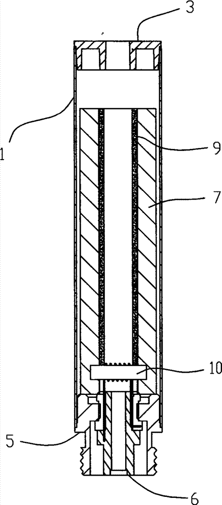
[0047] Such as Figure 5 , Figure 6 As shown, on the basis of including all the technical features in the specific embodiment 1, the main difference between this embodiment and the first embodiment is that it also includes a glass fiber tube 2, and the oil storage substance is wrapped in the glass fiber tube 2, the denser layer is close to the glass fiber tube 2, that is, the cotton cloth layer 9 is wrapped on the outer surface of the glass fiber tube 2.

[0048] Such as Figure 7 As shown, the connecting end of the fiberglass tube 2 and the threaded sleeve 1 is provided with an opening, and the opening divides the fiberglass tube 2 into two connecting pieces 21 and connecting pieces 22 (of course, it can also be divided into three, Four connecting pieces, the purpose of this embodiment being divided into two connecting pieces is to reduce the installation quantity of the wedges, make the assembly easier, and improve the efficiency of the installation process.), the heating...

specific Embodiment 3

[0052] Such as Figure 9 As shown, the main difference between this embodiment and the second embodiment is: the wedge piece 12 is a ring structure, and the wedge piece 12 is also provided with a pressure groove 121 and a pressure groove 122 . The purpose of setting the pressure grooves 121 and 122 is to facilitate the access of the wedge piece 12 during assembly.

[0053] Another example Figure 9 As shown, the ring of the wedge piece 12 is also provided with an opening, and the opening on the wedge piece 12 is provided with a chamfer.


PUM


Abstract

The invention discloses an atomizer for an electronic cigarette, and aims to provide the atomizer for the electronic cigarette, which is few in elements, simple in assembling process and low in cost. The implementation scheme is as follows: the atomizer for the electronic cigarette comprises an atomization sleeve, a suction nozzle cover, a thread bushing, an electrode retaining collar fixedly arranged in the thread bushing, an oil storage substance arranged in the atomization sleeve and a heating wire component, wherein an insulation ring is arranged between the thread bushing and the electrode retaining collar; the suction nozzle cover and the thread bushing are respectively in close fit with two ends of the atomization sleeve; two pins of the heating wire component are respectively connected with the thread bushing and the electrode retaining collar; the oil storage substance is formed by at least two layers with different densities; and the atomizer is exclusive of a glass fiber pipe. The invention further discloses an electronic cigarette comprising the atomizer.

Description

technical field [0001] The invention relates to an atomizer for an electronic cigarette, and also relates to an electronic cigarette including the atomizer. Background technique [0002] The electronic cigarettes on the market are equipped with an atomizer on the battery assembly, and a heating wire assembly for atomizing the e-liquid is installed in the atomizer. Atomizers in the prior art, as in the accompanying drawings figure 1 As shown, the atomizer includes an atomizing sleeve 1, a glass fiber tube 2 arranged in the atomizing sleeve 1, a suction nozzle cover 3, a threaded sleeve 5, an electrode ring 6 fixedly arranged in the screwed sleeve 5, and a package The oil storage material on the glass fiber tube 2, the heating wire assembly 10, an insulating ring 11 is arranged between the threaded sleeve 5 and the electrode ring 6, and the suction nozzle cover 3 and the threaded sleeve 5 are respectively arranged on the At both ends of the atomizing sleeve 1, an oil blockin...

Claims


Application Information

Patent Timeline
Patent Type & Authority Applications(China)
IPC IPC(8): A24F47/00A24F15/015A24F40/10A24F40/42A24F40/46A24F40/485
CPCA24F40/46A24F40/10A24F15/015A24F40/42A24F40/485
Inventor 李永海徐中立
Owner SHENZHEN FIRST UNION TECH CO LTD
Why Eureka
Try Eureka