
Interferometric system for complex image extraction

an interferometric system and image extraction technology, applied in the field of optical interferometric systems, can solve the problems of affecting the processing efficiency of optical interferometers, etc., and achieves the effects of reducing the number of optical interferometers

Inactive Publication Date: 2009-03-24
NAT RES COUNCIL OF CANADA
View PDF5 Cites 19 Cited by
  • Summary
  • Abstract
  • Description
  • Claims
  • Application Information

AI Technical Summary

Problems solved by technology

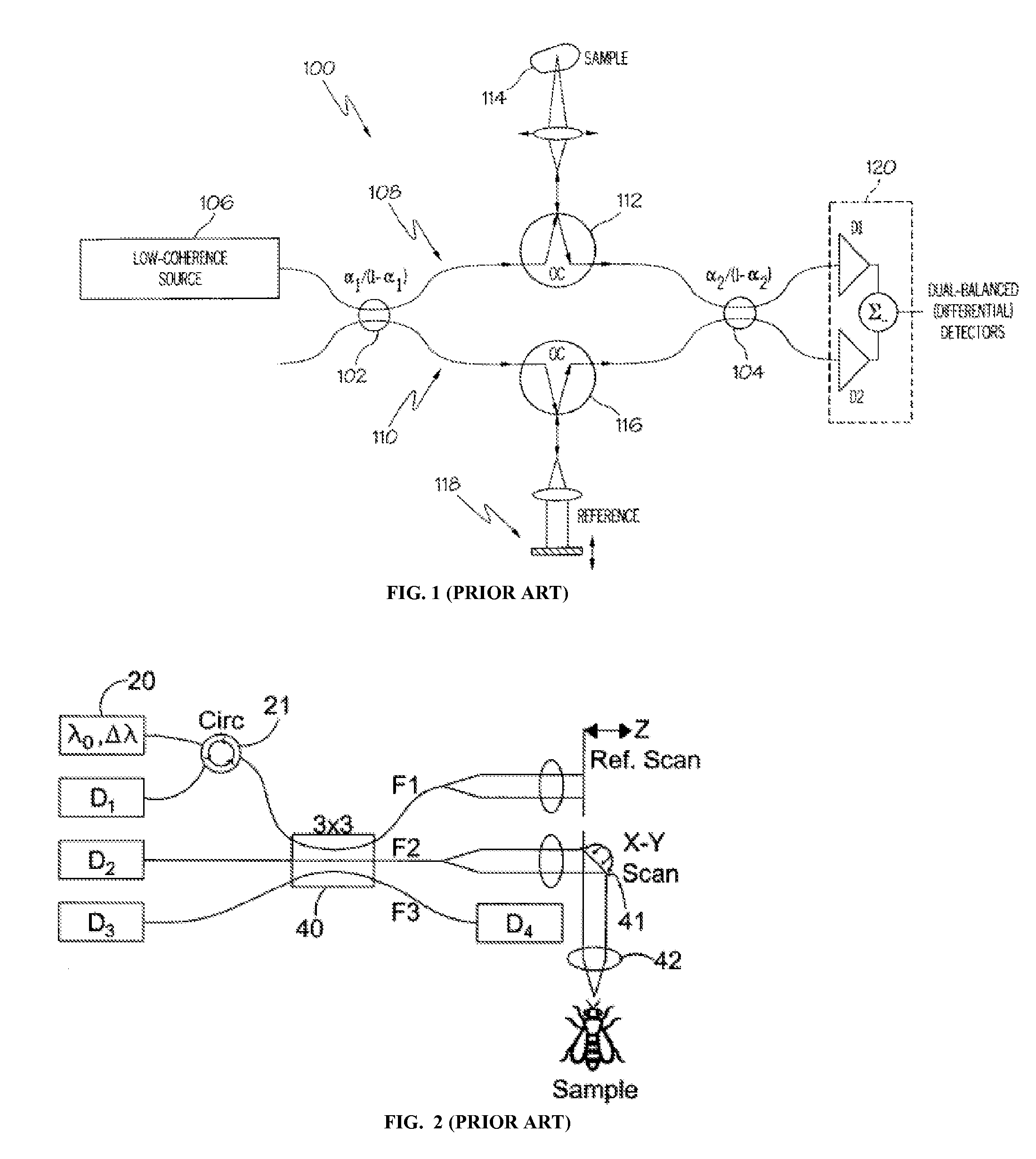
A limitation of the interferometric system 100, as well as many other prior-art interferometric systems used in Fourier domain OCT imaging, is that it provides only one of two quadrature components of the interferometric signal resulting from the mixing the sample and reference light, or, equivalently, only a real part of a complex interferometric signal, so that information carried by the imaginary part of the signal is lost.
One drawback resulting from this limitation of conventional single-channel OCT systems is the appearance of the co-called complex conjugate artifact, due to which positive and negative distances in an OCT scan are not resolved, so that only half of the potentially available imaging depth can be realized.
Another drawback of the prior-art single-channel OCT systems is that the detected interferometric signal typically depends on both the refractive and absorptive properties of the imaged sample, and it becomes difficult to separate them and obtain refractive and absorptive properties of the imaged sample individually.
This approach has considerable drawbacks, since it requires expensive widely-tunable sources of light for performing OCT measurements over a wide wavelength range, for example from 200 nm to 1000 nm, with a relatively small frequency step, and the results of KK-computations are very sensitive to the accuracy of the initial absorption spectra measurements.
One drawback of the OCT system shown in FIG. 2 is that it lacks balanced detectors that enable to eliminate common mode noise in system 100 shown in FIG. 1, and the description in '838 patent does not provide any clear way how the differential detection can be realized in the system described therein.
Another drawback of this system is that it is based on a Michelson configuration with a single coupler 40 functioning both as a beam splitter and a beam combiner, which does not allow the same flexibility as a Mach-Zehnder configuration in optimizing optical power splitting between the reference and sample arms.
Also, the '838 patent does not provide a way to obtain refractive and absorptive properties of the sample using the disclosed system.

Method used


Image

  • Interferometric system for complex image extraction
  • Interferometric system for complex image extraction
  • Interferometric system for complex image extraction

Examples


first embodiment

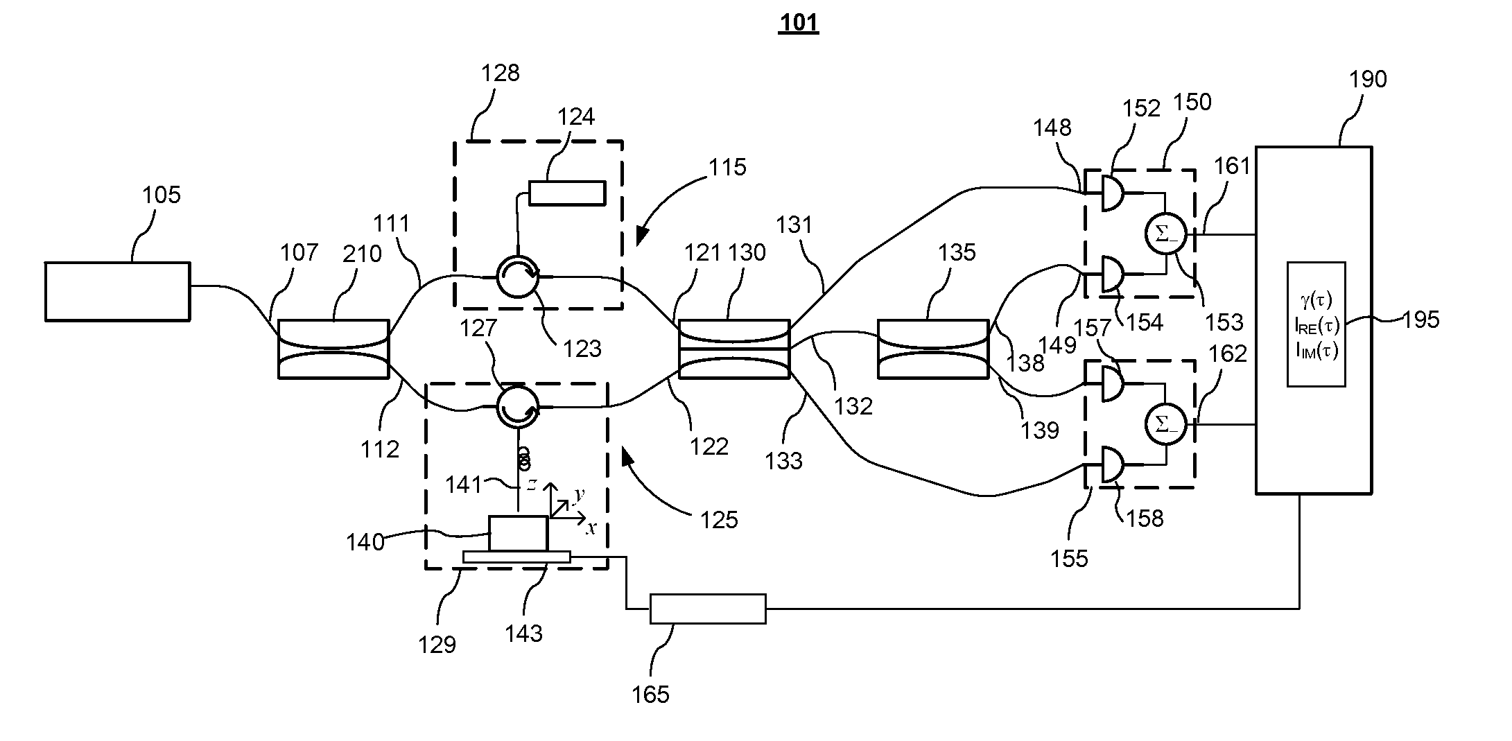
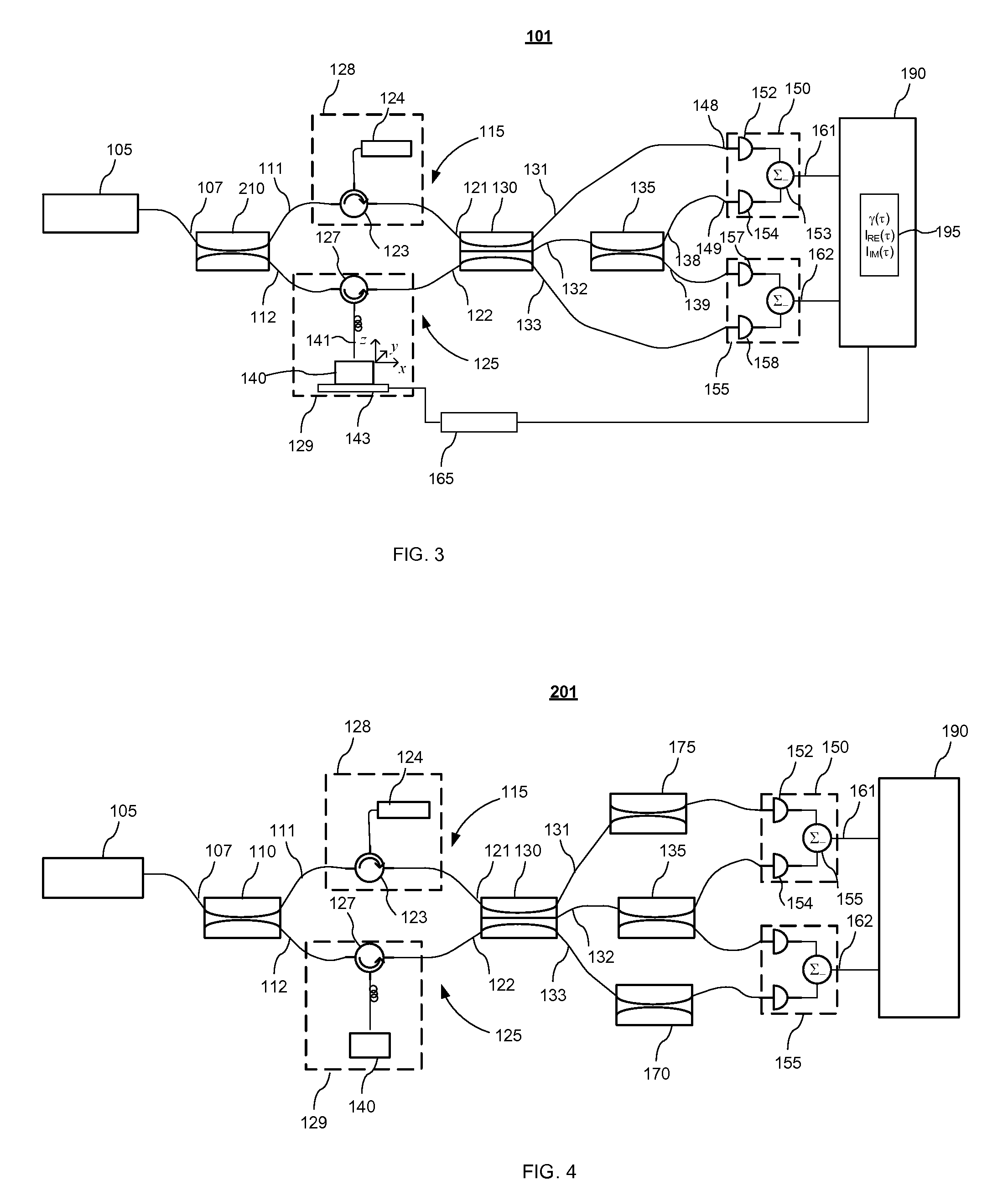
[0043]With reference to FIG. 3, in the invention an interferometric system 101 includes a Mach-Zehnder interferometer formed by a beamsplitter 210, hereinafter also referred to as the first beamsplitter, and a multi-port coupler 130, hereinafter also referred to as the first coupler. The beamsplitter 210 has an input port 107 and two output ports 111 and 112, which are coupled to respective input ports 121 and 122 of the first coupler 130 by two connecting arms 115 and 125. In the shown example the beam splitter 210 is embodied as a 2×2 waveguide, for example fiber-optic, directional coupler having one of the input ports unused and will also be referred to hereinafter as the 2×2 coupler 210; alternatively the beam splitter 210 can be embodied using bulk optics or any other suitable optical power splitting device known in the art. One of the connecting arms of the Mach-Zehnder interferometer, i.e. the first arm 115 includes adjustable time delay means 120 formed in this embodiment by...

second embodiment

[0060]With reference to FIG. 4, an alternative second embodiment of the invention provides an interferometric system 201 which is similar to the interferometric system 101 shown in FIG. 3, but includes two additional optical attenuators 170 and 175, in the shown configuration embodied as 2×2 couplers, that are coupled between the first 131 and third 133 ports of the 3×3 coupler 130 and respective optical input ports of the differential detectors 155 and 150, so as to equalize dc components of the optical signal at both ports of each of the differential detectors 150 and 155. In this embodiment, the differential detectors 150 and 155 are balanced so as to provide electrical output signals wherein the dc components are substantially canceled, thereby providing optimal cancellation of common mode noise.

[0061]In both embodiments, the ac, or interferometric components I1ac, I2ac of the first and second electrical signals that are output through the ports 161 and 162 have a phase shift Δφ...


PUM


Abstract

The invention provides an interferometric system and method for quadrature detection of optical characteristics of a sample. The system includes a Mach-Zehnder interferometer providing a variable optical delay between light collected from the sample and reference light. The Mach-Zehnder interferometer has an output M×N coupler with N≧3 output ports. Two differential detectors, each having two input ports coupled to a different two of the N output ports of the M×N coupler, produce first and second electrical signals having an interferometric phase shift. A processor is provided for computing real and imaginary parts of a complex refractive index of the sample from the first and second electrical signals by using complex deconvolution.

Description

CROSS-REFERENCE TO RELATED APPLICATIONS[0001]The present invention claims priority from U.S. Provisional Patent Application No. 60 / 832,612 filed Jul. 24, 2006, entitled “Apparatus and method for complex image extraction and restoration with application in optical coherence tomography (OCT) and optical low coherence reflectometry (OLCR)”, which is incorporated herein by reference.TECHNICAL FIELD[0002]The present invention relates to optical interferometric systems, and in particular to an interferometric system and method for simultaneously obtaining absorptive and refractive properties of a sample with a high signal to noise ratio.BACKGROUND OF THE INVENTION[0003]Optical Coherence Tomography (OCT) and Optical Low Coherence Reflectometry (OLCR) are interferometry-based techniques that have been successfully used in non-invasive and non-destructive analysis and imaging of structures in turbid media, especially in biological tissues. OLCR is a one-dimensional optical ranging technique ...

Claims


Application Information

Patent Timeline
Patent Type & Authority Patents(United States)
IPC IPC(8): G01B9/02
CPCG01N21/4795G01B9/0201G01B9/02091G01B9/02081G01B2290/45
Inventor CHANG, SHOUDEFLUERARU, COSTEL P.SHERIF, SHERIF S.
Owner NAT RES COUNCIL OF CANADA
Learn More