Stator assembly for an electrical machine

a stator and electrical machine technology, applied in the field of electric machines, can solve the problems of stator damage, plasticizing of the housing material and damage to the stator, and the creation of chips that cannot always be completely removed, so as to achieve fast and simple connection, special and economical production, and secure connection

Inactive Publication Date: 2009-03-31
ROBERT BOSCH GMBH
View PDF7 Cites 23 Cited by
  • Summary
  • Abstract
  • Description
  • Claims
  • Application Information

AI Technical Summary

Benefits of technology

[0007]Especially preferably, the stator also has at least one axially extending, inward- or outward-oriented bead. By providing an inward-oriented bead in the housing and in the stator, especially fast and simple connection of the two components to make the stator assembly is possible. The beads may be provided before installation of the stator in the housing, and then fixation of the stator in the housing is effected by means of metal-cutting, resilient clamping of the housing.
[0008]To meet especially close tolerances, especially for the inward- or outward-oriented side of the stator, the beads on the housing and the beads on the stator are preferably embodied such that in the installed state, the housing is connected to the stator at a plurality of connecting points. One gap each is embodied in the circumferential direction between the individual connecting points. Thus the housing and the stator are connected in metal-cutting, resilient and clamping fashion at only some points, and thus only very slight forces of deformation have to be exerted on the stator and the housing. This makes it possible to meet even very close positioning tolerances between the stator and the ball bearing seat and thus also the rotor.
[0010]For the sake of attaining the least possible deformation of the stator and housing and to enable a defined positioning, at a transition between a bead and the normal outer diameter of the stator there is a gap of the least possible size at this point between the housing and the stator in the installed state.
[0011]Preferably, a plurality of beads are embodied on the housing and on the stator and are spaced apart equally from one another in the circumferential direction. Especially preferably, four or six beads each, because of the measurability of the coaxiality, are formed on the housing and on the stator.
[0012]In another preferred embodiment of the invention, the length of the beads on the housing correspond in the axial direction to the length of the stator in the axial direction. As a result, an especially secure, simple connection between the stator and the housing can be made possible.
[0013]To further reduce component expenses for the electrical machine, a bearing for an armature shaft of the electrical machine is preferably formed integrally on the housing. Also preferably, securing openings with stop shoulders for the outer race of the ball bearing are additionally formed integrally on the housing, for securing the electrical machine.
[0014]The stator is preferably made from many stator laminations made of sheet steel, and the housing is likewise made from a steel sheet, so that during the operation of the electrical machine, no negative influences occur from loosening or high pressure at high and low temperature because of different thermal expansions, or of shrinkages in the cold of the housing and the stator. Also preferably, guide faces for securing a second bearing cap are embodied on the housing. In particular with a bearing cap integrated with the housing, for supporting the armature shaft, an especially high coaxiality between the stator and an armature supported on the housing can be achieved.
[0016]The present invention also relates to an electrical machine having a rotor-stator relationship according to the invention, and in particular to an electric motor, such as an asynchronous motor, in which there is the least possible air gap between the armature and the stator.

Problems solved by technology

This can lead to indefiniteness of the stator fixation, and can even cause plasticizing of the housing material and damage to the stator.
Such remachining operations are not only expensive but also cause the creation of chips that cannot always be completely removed.
If unremoved chips get between the armature shaft and the stator during operation, this can cause seizing or blocking of the rotor and a short circuit of the stator winding wires.

Method used


Image

  • Stator assembly for an electrical machine
  • Stator assembly for an electrical machine
  • Stator assembly for an electrical machine

Examples


Embodiment Construction

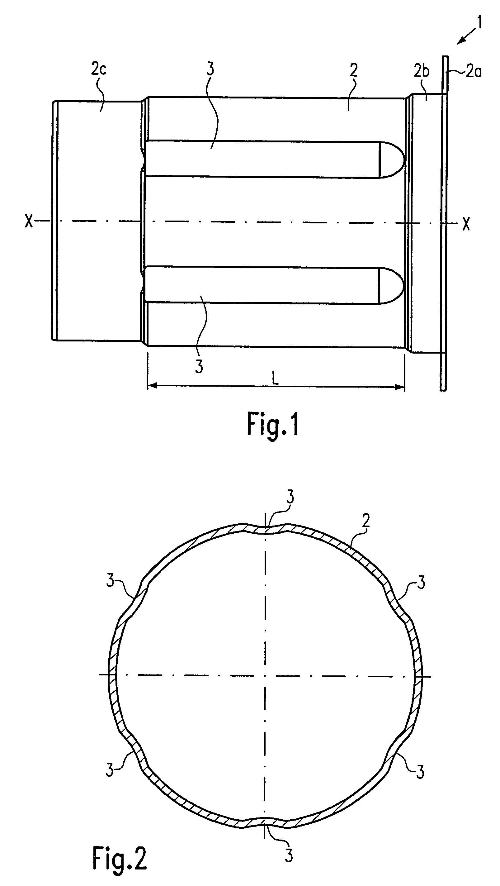
[0028]Below, referring to FIGS. 1 through 6, a stator assembly 1 in a first exemplary embodiment of the present invention includes a substantially cylindrical housing 2 and a stator 4.

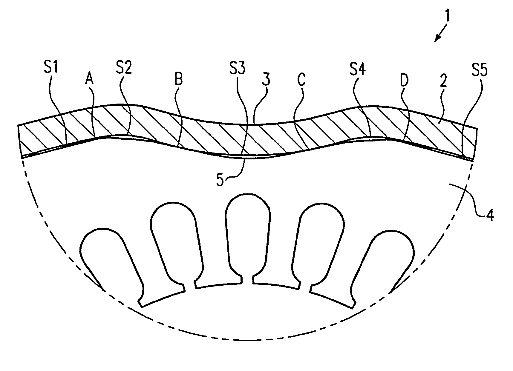
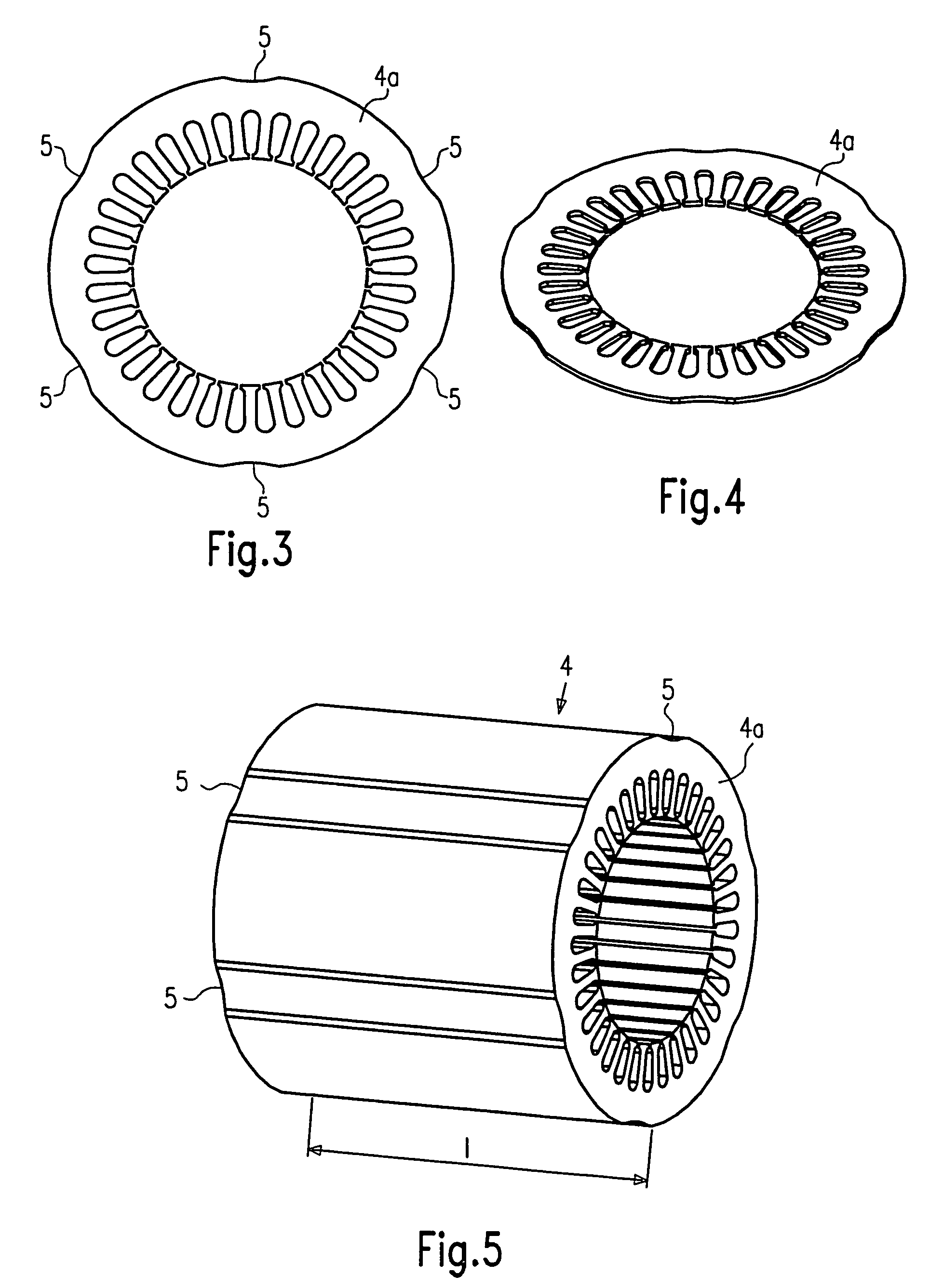
[0029]FIG. 2 shows a sectional view of the housing 2. In the axial direction X-X, six inward-oriented beads 3 are embodied. The beads 3 are disposed along the circumference of the housing 2, at equal spacings from one another. In the axial direction X-X, the beads 3 have a length L, which corresponds to a length 1 of the stator 4 (see FIGS. 1 and 5). The stator 4 is put together in a known way from many individual stator laminations 4a. As can be seen particularly from FIG. 3, there are likewise six inward-oriented beads or notches 5, spaced equally apart along the circumference, embodied on the outer circumference of each stator lamination 4a.

[0030]FIG. 6 now shows the installed state of the stator lamination packet in the housing 2. The stator laminations are disposed in the housing 2 such that the ...


PUM


Abstract

The present invention relates to a stator assembly for an electrical machine, including a housing and a stator, in which the housing has at least one inward-oriented bead extending in the axial direction.

Description

CROSS-REFERENCE TO RELATED APPLICATIONS[0001]This application is a 35 USC 371 application of PCT / EP 2004 / 053484 filed on Dec. 15, 2004.BACKGROUND OF THE INVENTION[0002]1. Field of the Invention[0003]This invention relates to electrical machines, and more particularly to an improved stator assembly for an electrical machine.[0004]2. Description of the Prior Art[0005]Electrical machines are well known in the prior art, for instance in the form of electric motors. Such electric motors often use stator packets which are put together from many stator laminations. These stator laminations are held together by means of a pole housing. The pole housing is shrunk onto the stator laminations by a shrinking process, as a result of which the laminations are held and fixed. Because of the different materials, during motor operation different thermal expansions occur for the housing and the stator laminations. This can lead to indefiniteness of the stator fixation, and can even cause plasticizing...

Claims


Application Information

Patent Timeline
Patent Type & Authority Patents(United States)
IPC IPC(8): H02K1/12F16D1/108H02K1/18H02K5/04H02K5/16H02K5/167
CPCF16D1/108H02K1/185H02K5/04H02K5/161
Inventor LUNG, EBERHARDECKERT, OLIVERCHOMBO VIDALES, RICARDOBAUCH, CHRISTANGUYEN, QUOC-DATNGUYEN, NGOC-THACH
Owner ROBERT BOSCH GMBH
Why Eureka
Try Eureka