
Bidirectional communication system

a communication system and bidirectional technology, applied in the field of bidirectional communication systems, can solve the problems of often exceeding the bandwidth demand of the line (e.g., fiber pair) connecting the nodes/terminals

Active Publication Date: 2009-03-31
CIENA
View PDF26 Cites 15 Cited by
  • Summary
  • Abstract
  • Description
  • Claims
  • Application Information

AI Technical Summary

Benefits of technology

The patent text describes a system for improving the cost and utilization of optical communication networks by measuring and compensating for fiber loss and dispersion in the network. The invention provides methods and systems for measuring the fiber loss and compensating for it by using line amplifier nodes and dispersion compensating modules. The system also includes add / drop nodes for adding or dropping signals from the lines. The invention helps to reduce the number of expensive components, such as optical line amplifiers, and improve the system cost and utilization of the existing infrastructure.

Problems solved by technology

However, the bandwidth capacity of the lines (e.g., fiber pairs) connecting the nodes / terminals often is greater than the bandwidth demand.

Method used


Image

  • Bidirectional communication system
  • Bidirectional communication system
  • Bidirectional communication system

Examples


Embodiment Construction

[0020]Aspects of the invention are disclosed in the following description and related drawings directed to specific embodiments of the invention. Alternate embodiments may be devised without departing from the spirit or the scope of the invention. Additionally, well-known elements of the invention will not be described in detail or will be omitted so as not to obscure the relevant details of the invention.

[0021]The expression communicates, coupled, connection, and connected as used herein refers to any connection, coupling, link and the like by which optical signals carried by one optical system element are imparted to the communicating element. Further, the devices described are not necessarily directly connected to one another and may be separated by intermediate components or devices.

[0022]The term “service channel” as used herein refers to a wavelength of an optical communication system such as a WDM, SONET or SDH-based system that is used to carry operational, administrative, m...


PUM


Abstract

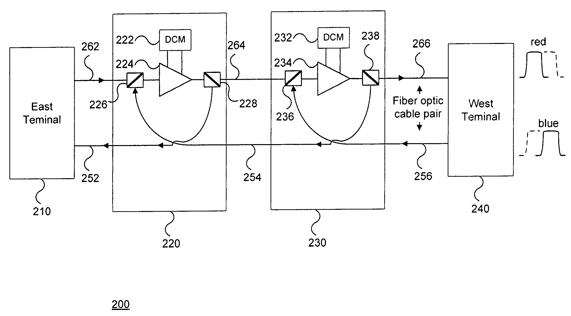
A bidirectional communication system is disclosed. A single optical line amplifier is used to amplify signals in both the east and west directions. Additionally, a single dispersion compensation module is used to compensate for fiber dispersion in both directions. Using a single optical line amplifier and a single dispersion compensation module for both directions allows for reduction in the number of optical line amplifiers used in a given network.

Description

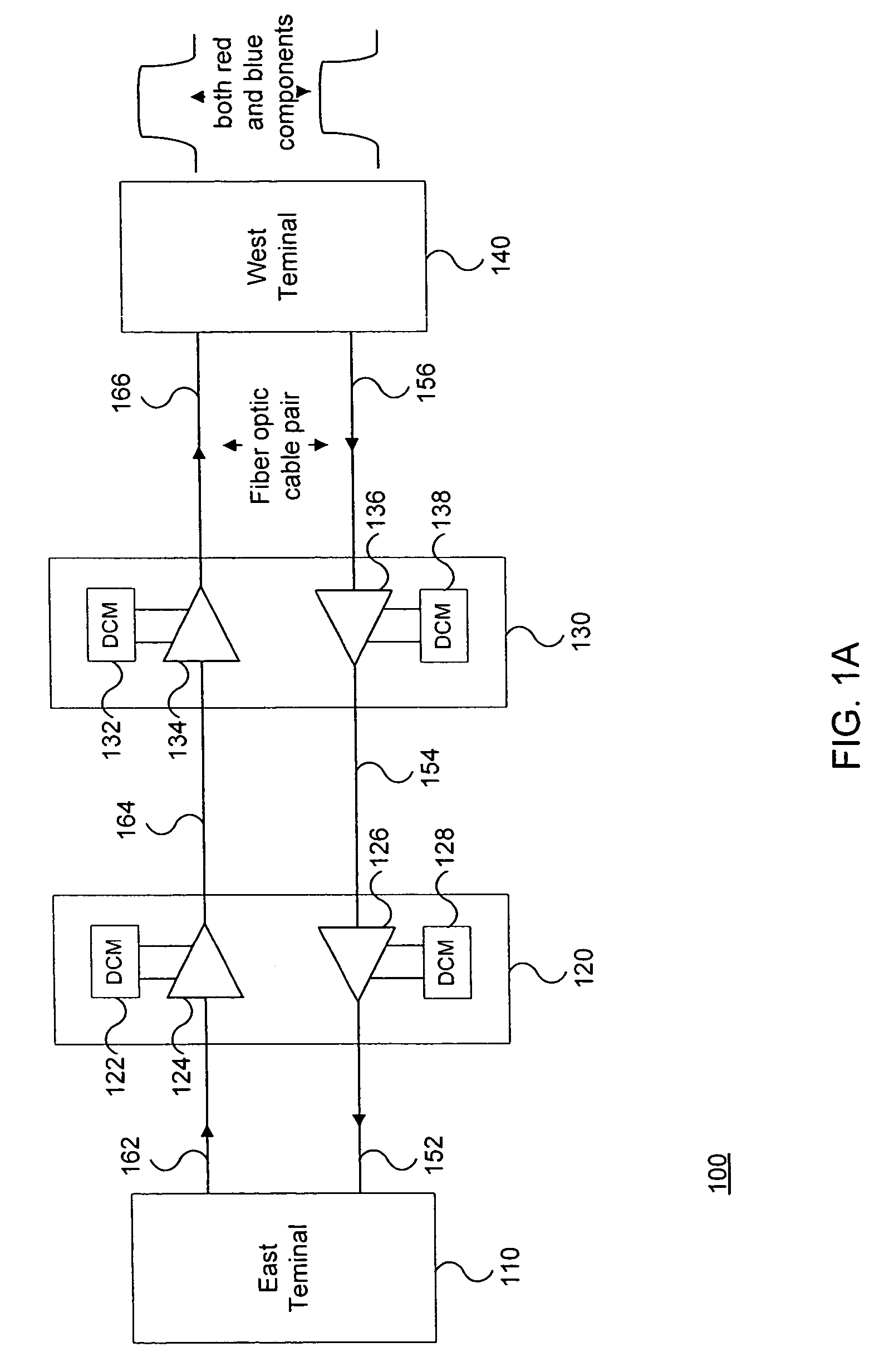
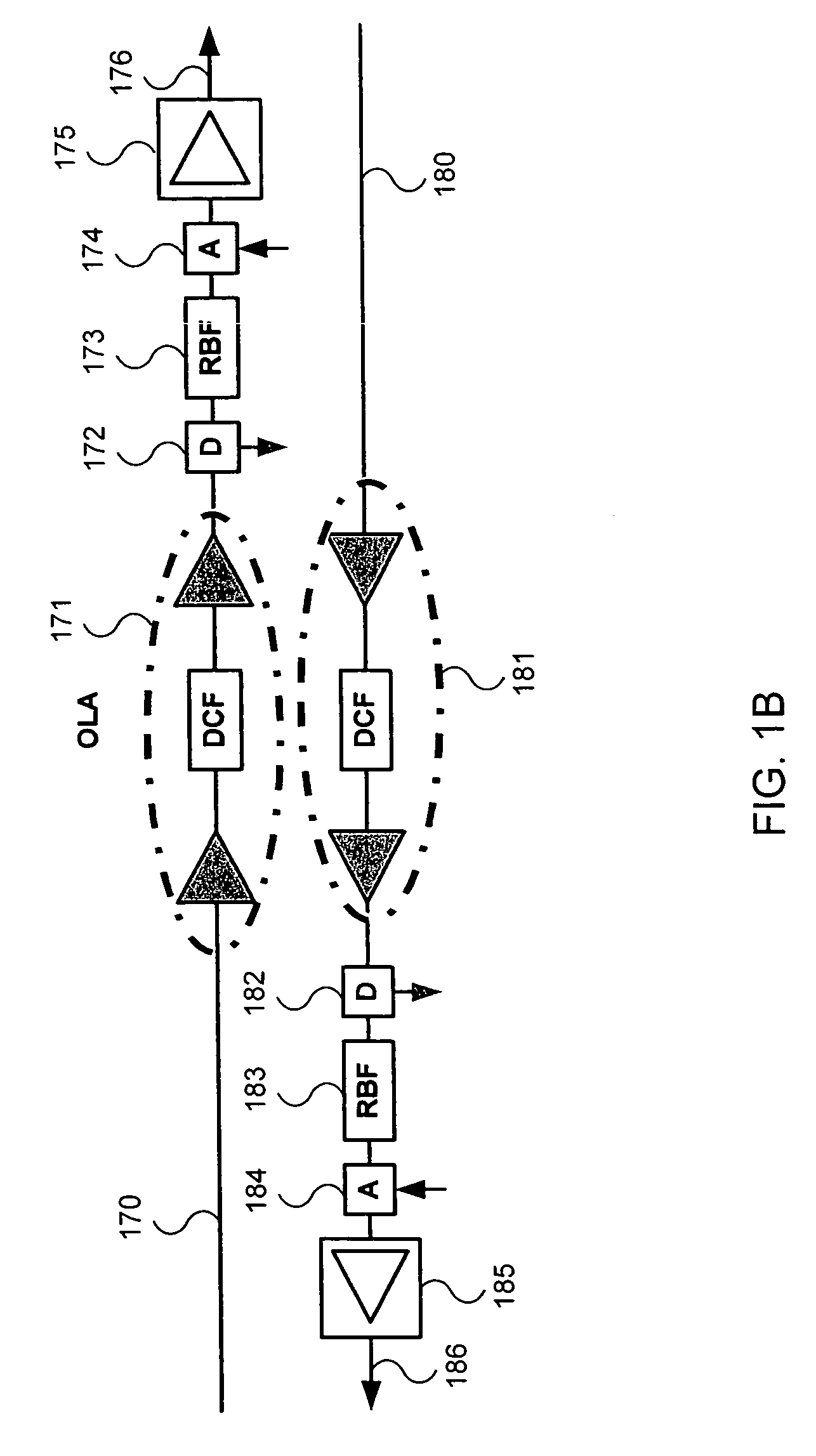
CROSS-REFERENCE TO RELATED APPLICATIONS[0001]This application claims priority under 35 U.S.C. § 119(e) on U.S. Provisional Patent Application No. 60 / 591,095 filed on Jul. 27, 2004, which is incorporated herein by reference in its entirety and on U.S. Provisional Patent Application No. 60 / 604,487 filed on Aug. 26, 2004, which is incorporated herein by reference in its entirety.BACKGROUND OF THE INVENTION[0002]In current large-scale networks, information flows through a series of nodes / network elements in the network from one location or site to another. FIG. 1A illustrates a related art system 100 that has an east 110 and west 140 terminal. The east 110 and west 140 terminals communicate via lines (e.g., optical fiber pairs) that run between the terminal, as illustrated (e.g., lines 152-156 and 162-166). east 110 and west 140 terminals can be located a significant distance apart. Accordingly, line amplifier nodes (e.g., 120, 130) can be interposed between the terminals (e.g., every 4...

Claims


Application Information

Patent Timeline
Patent Type & Authority Patents(United States)
IPC IPC(8): H04B10/08H04B10/00H04B10/12
CPCH04B10/25133H04B10/2918H04B2210/003H04B2210/256H04B10/298
Inventor SRIDHAR, BALAKRISHNANFRANKEL, MICHAEL Y.BHATNAGAR, VIPUL
Owner CIENA
Learn More