Eureka AIR delivers breakthrough ideas for toughest innovation challenges, trusted by R&D personnel around the world.

Lead fixation tool

a technology of lead fixation and wrench, which is applied in the field of lead fixation tools for implantable medical devices, can solve the problems of cumbersome “wrapping” action required to use the wrench, large size of the wrench, and large surgical field, and achieve the effect of facilitating the insertion of the styl

Inactive Publication Date: 2009-03-31
MEDTRONIC INC
View PDF8 Cites 23 Cited by
  • Summary
  • Abstract
  • Description
  • Claims
  • Application Information

AI Technical Summary

Problems solved by technology

Generally, such a wrench is relatively large and encumbers a large portion of the surgical field.
Furthermore, the “wrapping” action required to use the wrench may be cumbersome.

Method used


Image

  • Lead fixation tool
  • Lead fixation tool
  • Lead fixation tool

Examples


Embodiment Construction

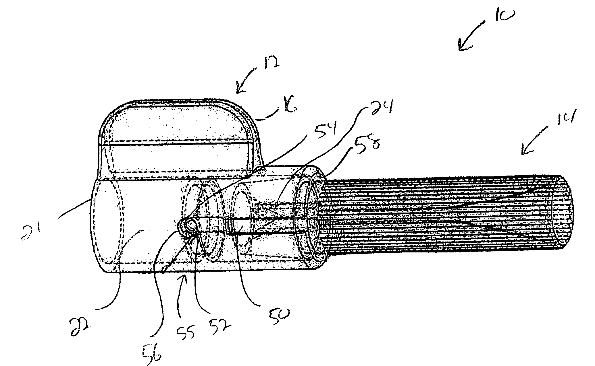
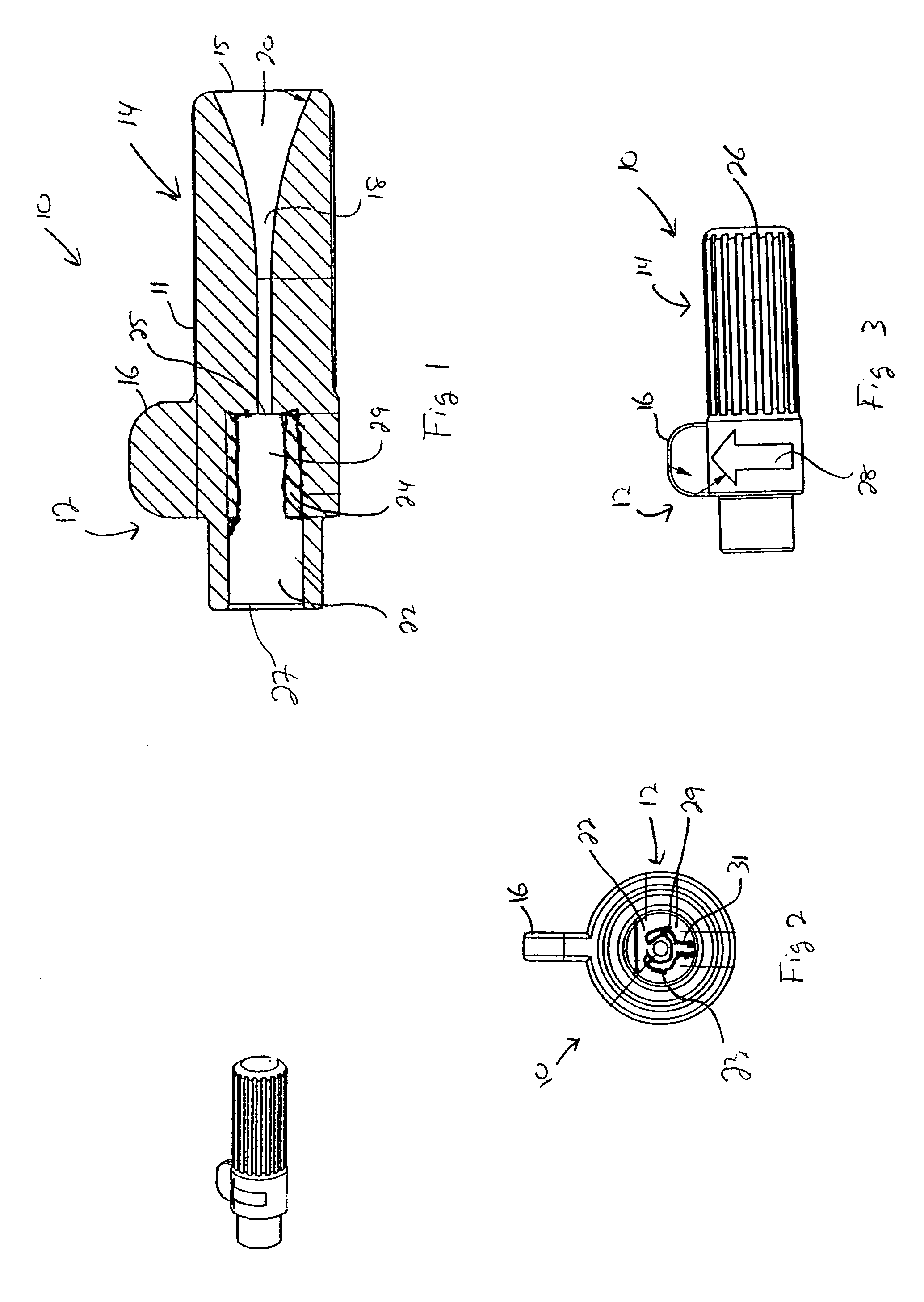
[0023]FIG. 1 is a side sectional view of a fixation tool 10. The fixation tool 10 includes a distal portion 12 and proximal portion 14 that to form a housing 11. As illustrated, the proximal portion 10 and the distal portion 12 are integral and provide a rigid tool 10. In other embodiments discussed below, the proximal portion 10 and the distal portion 12 are rotatably coupled together.

[0024]The fixation tool 10 can be fabricated from any suitable material, including plastic or metal, that can be properly sterilized for use in a surgical field. In one embodiment, the fixation tool 10 is an integral unit that is molded from plastic. In other embodiments, separate components are coupled together to form the fixation tool 10.

[0025]As illustrated in FIGS. 1 and 2, the fixation tool 10 includes a handle 16 disposed on the distal portion 12. The handle 16 is a relatively narrow tab that extends outward from the distal portion 12. The handle 16 can be used as a gripping surface to engage t...


PUM


Abstract

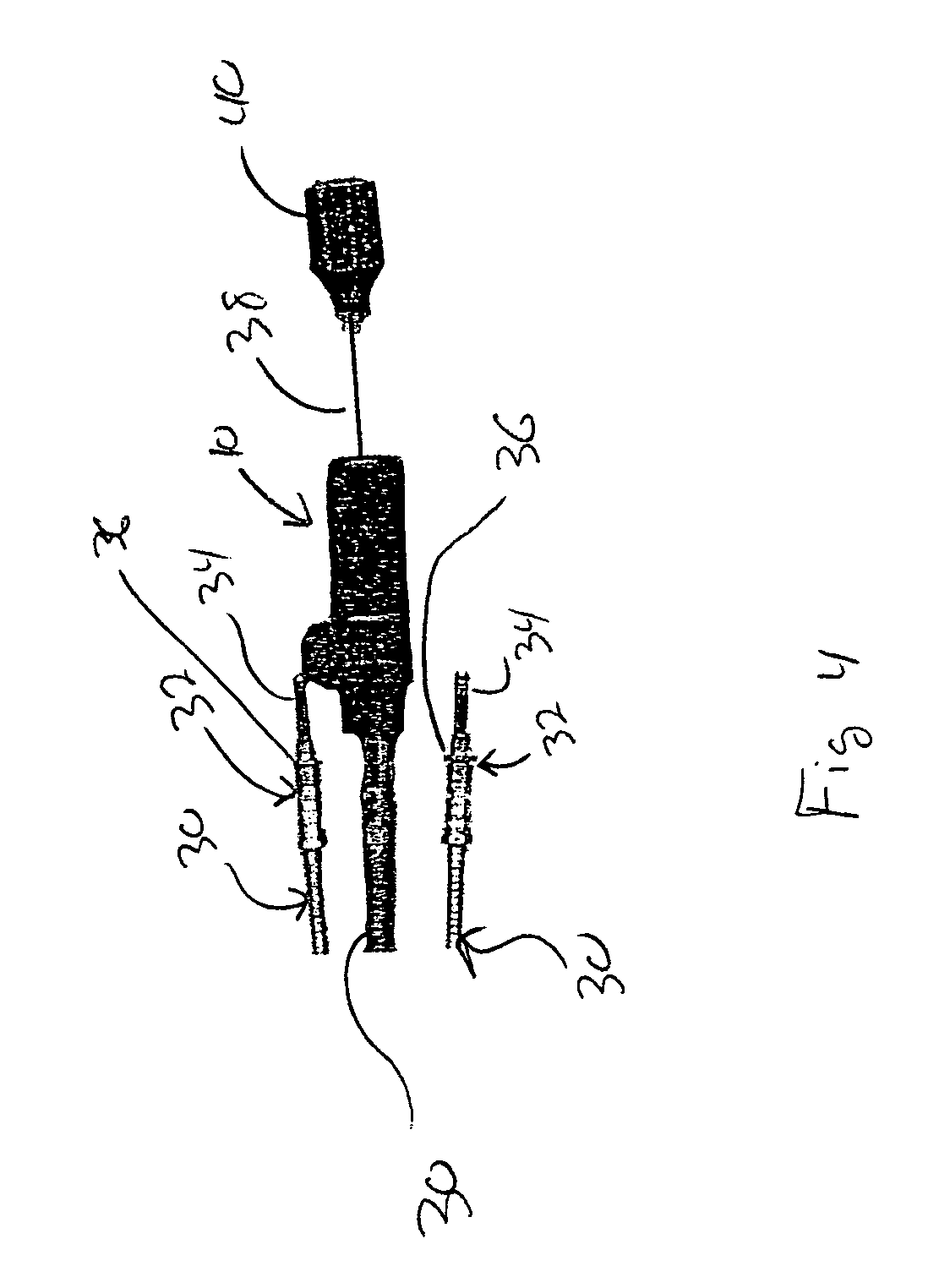
A lead fixation tool includes a tapered opening for receiving and guiding a stylet into a lead. The fixation tool also includes an engagement mechanism for gripping a portion of the lead connector so that rotation of the tool causes rotation of an active fixation tip, such as a helical tip, coupled with the lead.

Description

BACKGROUND OF THE INVENTION[0001]1. Field of the Invention[0002]The present invention generally relates to implantable medical devices. More specifically, the present invention relates to leads for implantable medical devices.[0003]2. Description of the Related Art[0004]Various implantable medical devices (IMD) utilize leads to deliver electrical stimulation to tissue, receive sensed electrical impulses from tissue, or transfer other sensor data indicative of a physical parameter. For example, implantable cardiac pacemakers, cardioverters, or defibrillators commonly have one or more leads connecting the device to cardiac tissue. The leads are often passed through a vein and guided into an atrial or ventricular chamber of the heart. Once so located, the distal end of the lead is properly positioned and often is secured.[0005]Various techniques are employed to secure the distal end of the lead within the heart. For example, some lead tips include tines that engage fibrous tissue along...

Claims


Application Information

Patent Timeline
Patent Type & Authority Patents(United States)
IPC IPC(8): A61N1/00A61B19/00B23Q3/12A61N1/05
CPCA61N1/057Y10T279/17351A61N2001/058
Inventor HONECK, JORDON D.
Owner MEDTRONIC INC
Why Eureka
Eureka Blog
Learn More