Active fixation assembly for an implantable device

a technology of fixation assembly and implantable device, which is applied in the direction of external electrodes, internal electrodes, therapy, etc., can solve the problem that the size of the drug plug and the collar becomes incompatible with the lead siz

Inactive Publication Date: 2005-03-31
CARDIAC PACEMAKERS INC
View PDF18 Cites 11 Cited by
  • Summary
  • Abstract
  • Description
  • Claims
  • Application Information

AI Technical Summary

Problems solved by technology

However, as leads become smaller, the size of the drug plugs and collars becomes incompatible with the lead size.

Method used


Image

  • Active fixation assembly for an implantable device
  • Active fixation assembly for an implantable device
  • Active fixation assembly for an implantable device

Examples


Embodiment Construction

[0025] In the following detailed description, reference is made to the accompanying drawings which form a part hereof, and in which is shown by way of illustration specific embodiments in which the invention may be practiced. These embodiments are described in sufficient detail to enable those skilled in the art to practice the invention, and it is to be understood that other embodiments may be utilized and that structural changes may be made without departing from the spirit and scope of the present invention. Therefore, the following detailed description is not to be taken in a limiting sense, and the scope is defined by the appended claims.

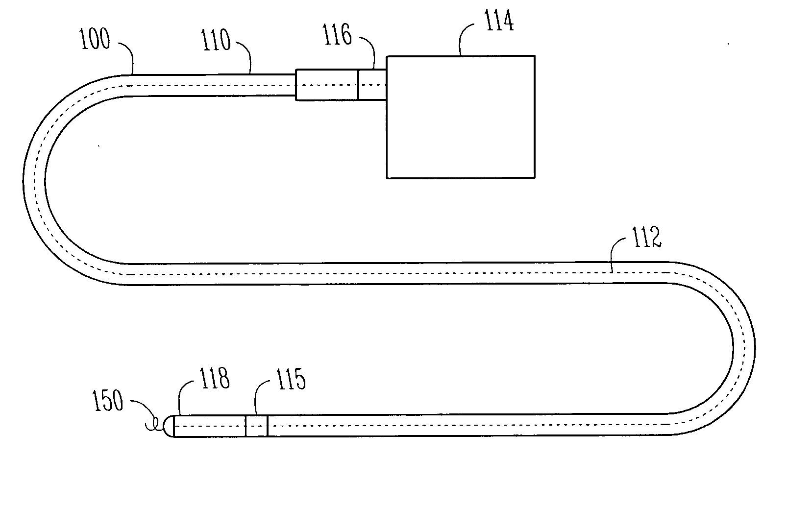
[0026] An implantable device 100, such as a lead for use with an electrical stimulator 114, is illustrated in FIG. 1. The implantable device 100 includes a lead body 110, an elongate conductor 112 contained within the lead body 110. The lead body 110 extends from a proximal end 116 to a distal end 118. The proximal end 116 of the lead is elect...


PUM


Abstract

An implantable device such as a lead is adapted for implantation on or about the heart and for connection to a system for monitoring or stimulating cardiac activity. The implantable device includes an active fixation assembly for securing the device to tissue. The active fixation assembly includes one or more recessed portions therein.

Description

TECHNICAL FIELD [0001] Leads for conducting electrical signals to and from the heart, and more particularly, a fixation assembly for coupling a lead with tissue. TECHNICAL BACKGROUND [0002] Pacemaker leads represent the electrical link between the pulse generator and the heart tissue which is to be excited. These pacemaker leads include single or multiconductors that are connected to an electrode in an electrode assembly at a distal end of a pacing lead. Typically, a terminal member is mounted within a flexure sleeve at the proximal end of the pacing lead and connected to the proximal end of the conductor. [0003] After the electrode assembly is positioned at a desired location within the heart, it is desirable to provide some method for securing the electrode assembly at that location. Mechanical fixation devices are used to firmly anchor the electrodes in the heart. One type of mechanical fixation device used is a corkscrew, or a helix. The helix is extended and screwed into the he...

Claims


Application Information

Patent Timeline
Patent Type & Authority Applications(United States)
IPC IPC(8): A61N1/05
CPCA61N1/0575
Inventor KAWULA, PAULKNAPP, CHRISTOPHER P.WINELAND, CAROLYN
Owner CARDIAC PACEMAKERS INC
Why Eureka
Try Eureka