Traffic cone apparatus and method of production

a technology of traffic cones and cones, which is applied in the direction of roads, roads, construction, etc., to achieve the effects of preventing damage to the tires of passing vehicles, different engineering characteristics, and high flexibility and durability

Inactive Publication Date: 2009-04-07
THREE D PLASTICS
View PDF21 Cites 16 Cited by
  • Summary
  • Abstract
  • Description
  • Claims
  • Application Information

AI Technical Summary

Benefits of technology

[0018]The presently described and illustrated traffic cone apparatus has a compression molded base portion made of ground tire bits and an injection molded or flow coated cone portion co-molded with the completed base portion wherein the co-molding process joins the cone portion to the base portion mechanically. The base is compression molded of ground bits of shredded tires into a preferably rectangular shape having relatively high specific weight and low cost, while the co-molded upper cone portion is made of a highly flexible and light weight polymer. The cone is co-injection molded with the base so as to engage the base with connector elements gripping apertures in the base so that the two parts are inseparable.
[0020]Another objective is to provide a traffic cone having high durability and yet produced at lowest cost.

Problems solved by technology

A traffic cone is a challenge to manufacture economically.

Method used


Image

  • Traffic cone apparatus and method of production
  • Traffic cone apparatus and method of production
  • Traffic cone apparatus and method of production

Examples


first embodiment

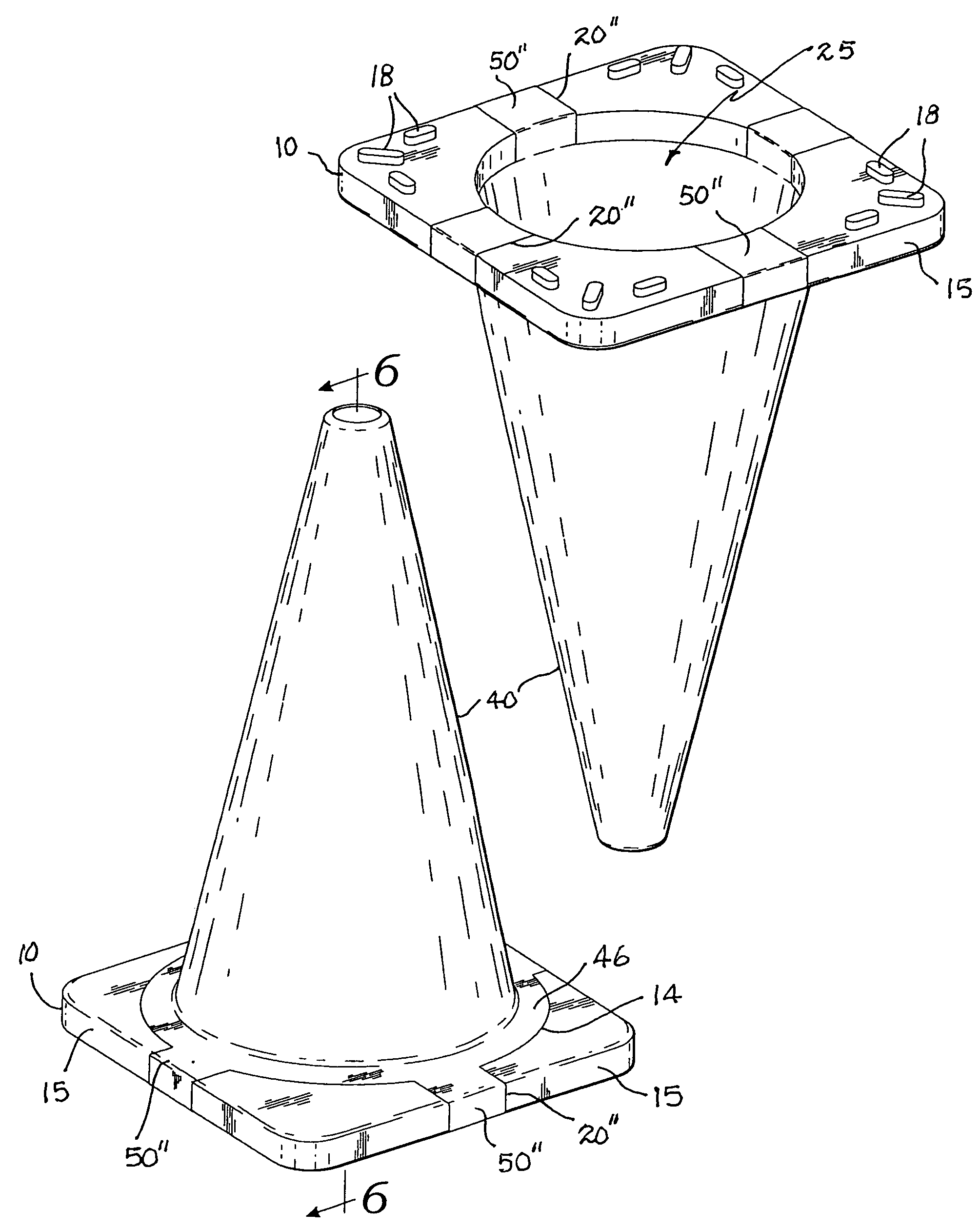
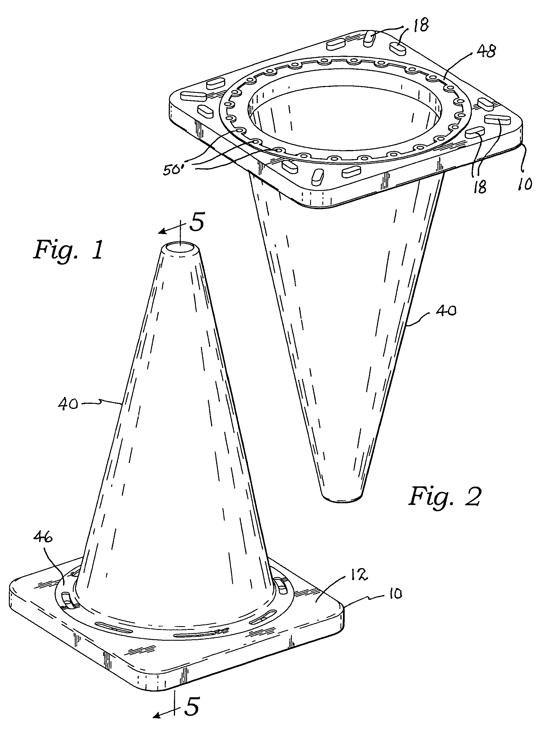
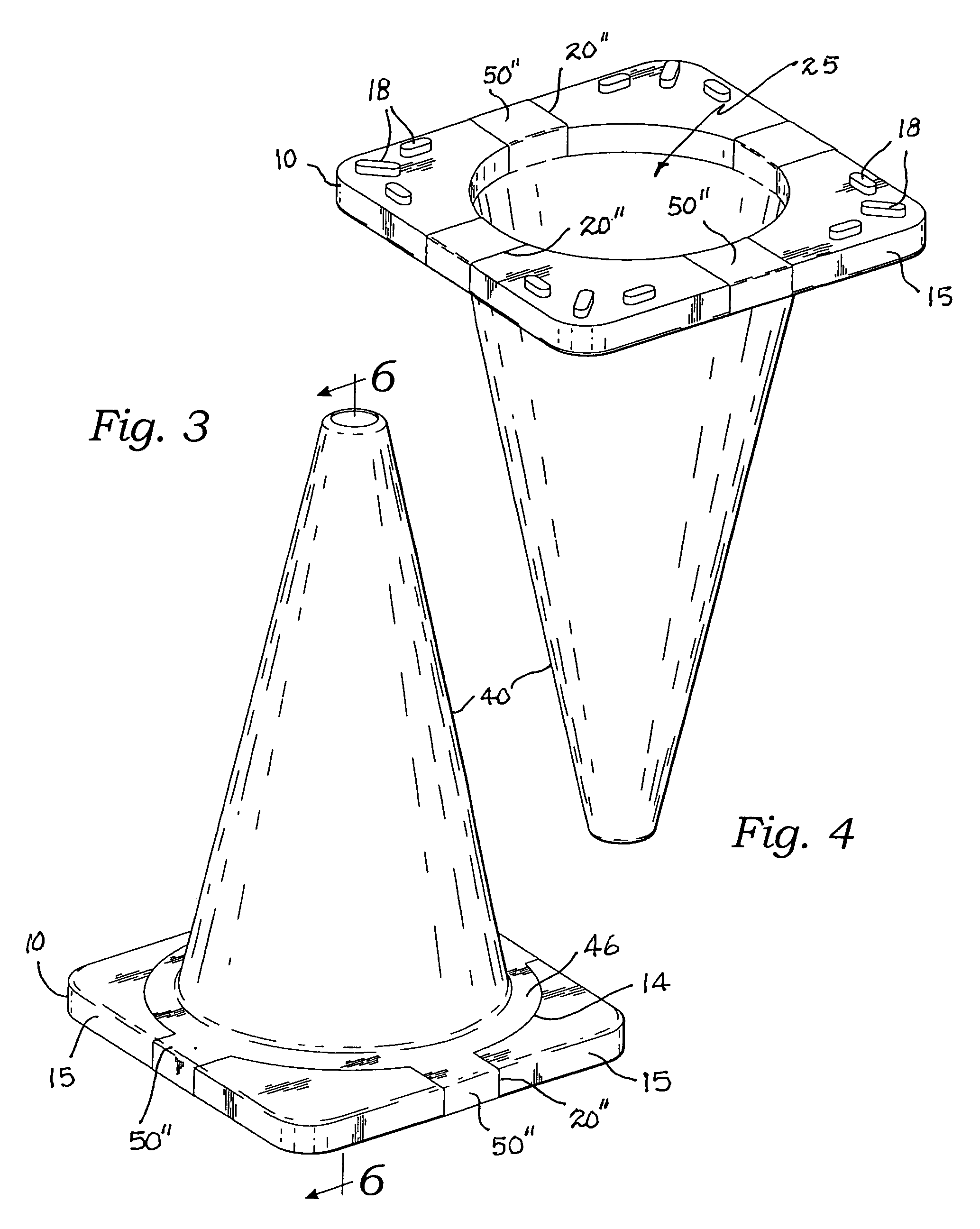
[0035]The cone 40 is an injection molded right circular hollow cone defining an upright wall 42. The wall 42 terminates upwardly with an apex 44 and downwardly with an annular flange 46 which sits within the well 14 of the base 10. This configuration and arrangement is clearly shown in FIGS. 1, 2 and 5 in a first embodiment, and FIGS. 3, 4 and 6 in a second alternate embodiment.

[0036]In both the first and the second embodiments, a plurality of injection molded connectors referred to generally with numeral 50 are integrally joined with the annular flange 46 and extend within the plurality of apertures 20 thereby mechanically engaging the cone 40 with the base 10.

[0037]In the first embodiment, the apertures form a circular arrangement of through holes 20′ extending from the top surface 12 to the bottom surface 16, as best seen in FIG. 5. In this embodiment, the connectors 50 form a circular arrangement of plugs 50′ integral with the annular flange 46 and extending within the through h...

second embodiment

[0038]In the second embodiment, the apertures are preferably grooves 20″ as best seen in FIG. 3, extending from the well 14, across the top surface 14 and around side edges 15 of the base 10. In this embodiment, the connectors 50 are injection molded strips 50″ extending within the grooves 20″, around the side edges 15 of the base 10 and also through a central hole 25 in the base 10 and across the bottom surface 16 of the base 10 thereby encircling the base 10. Preferably, four such strips 50″ are used and collectively are molded integrally with a cone 40 thereby mechanically securing the cone 40 with the base 10.

[0039]The usage of “apertures” herein is taken from the American Heritage Dictionary of the English Language, Third Edition, in its broadest sense of the word, i.e., “an opening such as a hole, gap, or slit.” Under this definition, both the holes described in the first embodiment below, and the grooves described in the second embodiment are included as apertures. As well, a...


PUM


Abstract

A traffic cone apparatus for controlling traffic has a molded base and a molded cone. The base is compression molded of bits of shredded tires into a preferably rectangular shape. The cone is co-injection molded with the base so as to engage the base with connector elements gripping apertures in the base.

Description

CROSS-REFERENCE TO RELATED APPLICATIONS[0001]Not applicable.STATEMENT REGARDING FEDERALLY SPONSORED RESEARCH OR DEVELOPMENT[0002]Not applicable.THE NAMES OF THE PARTIES TO A JOINT RESEARCH AGREEMENT[0003]Not applicable.INCORPORATION-BY-REFERENCE OF MATERIAL SUBMITTED ON A COMPACT DISC[0004]Not applicable.REFERENCE TO A “MICROFICHE APPENDIX”[0005]Not applicable.BACKGROUND OF THE INVENTION[0006]1. Field of the Present Disclosure[0007]This disclosure relates generally to traffic control apparatus and more particularly to a traffic cone made of two parts, a base of compressed tire fragments and a cone made of a plastic material or plastersol co-molded with the base such that the cone is mechanically engaged with the base.[0008]2. Description of Related Art Including Information Disclosed under 37 CFR 1.97 and 1.98[0009]Flamingo et al, 20060016383, discloses a traffic cone system including a base, a sleeve, and a retainer. The retainer substantially secures the sleeve relative to the bas...

Claims


Application Information

Patent Timeline
Patent Type & Authority Patents(United States)
IPC IPC(8): E01F9/012
CPCE01F9/0122E01F9/654E01F9/688
Inventor DVORACEK, JOE
Owner THREE D PLASTICS
Why Eureka
Try Eureka