Systems for detecting and tracking of objects and co-registration

Inactive Publication Date: 2016-07-07
ANGIOMETRIX CORP
View PDF2 Cites 39 Cited by
  • Summary
  • Abstract
  • Description
  • Claims
  • Application Information

AI Technical Summary

Benefits of technology

[0007]Disclosed are efficient methods to create a linearized view of a body lumen with the help of multiple image frames. In reality a lumen has a trajectory in 3-D, but only a 2-D projected view is available for viewing. The linearized view unravels this 3-D trajectory thus creating a linearized map for every point on the lumen trajectory as seen on the 2-D display. In one mode of the invention, the trajectory is represented as a linearized display along 1-dimension. This linearized view is also combined with lumen measurement data and the result is displayed concurrently on a single image referred

Problems solved by technology

While IVUS and OCT give a good estimate of the length and cross-sectional area of a lesion, one problem is that when the treatment is delivered it does not preserve position.
There is no existing mechanism to determine if the stent is positioned correctly at the diseased site.
The other problem is that the primary display used by physicians to view the X-ray images during diagnosis and treatment is typically a 2-D image taken from a certain angle and with a certain zoom factor.
This makes it difficult to accurately judge actual lengths from an X-ray image.
Even in this lat

Method used


Image

  • Systems for detecting and tracking of objects and co-registration
  • Systems for detecting and tracking of objects and co-registration
  • Systems for detecting and tracking of objects and co-registration

Examples


Example

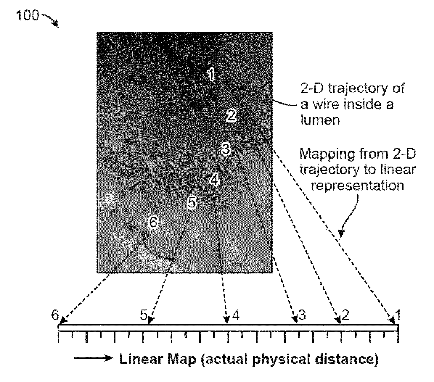
[0071]Here we describe methods to process the 2-D images to arrive at a linearized representation of a lumen of a moving organ. Illustrations of the proposed methods are shown for intervention of the coronary artery. A linear map is a mapping from a point on the curved trajectory of a lumen (or the wire inserted into the lumen) to actual linear distance measured from a reference point. This is shown in the schematic 100 in FIG. 1.

[0072]Many cardiac procedures involve the insertion of a lumen assessment device such as IVUS, OCT and LFR (see e.g., U.S. Pat. No. 8,374,689 B2 which is incorporated herein by reference in its entirety and for any purpose). In most of these cases, there is a need to co-register the position of the assessment device on a previously captured X-ray image that is usually also an angiographic image. This reference image is typically also used by the physician during a possible following intervention procedure such as angioplasty and stent deployment. A correct ...


PUM


Abstract

Systems for detecting and tracking of objects and co-registration are described which utilizes methods to create a linearized view of a lumen using multiple imaged frames. In reality a lumen has a trajectory in 3-D, but only a 2-D projected view is available for viewing. The linearized view unravels this 3-D trajectory thus creating a linearized map for every point on the lumen trajectory as seen on the 2-D display. In one mode of the invention, the trajectory is represented as a linearized display along 1 dimension. This linearized view is also combined with lumen measurement data and the result is displayed concurrently on a single image. In another mode of the invention, the position of a treatment device is displayed on the linearized map in real time. In a further extension of this mode, the profile of the lumen dimension is also displayed on this linearized map.

Description

CROSS-REFERENCE TO RELATED APPLICATIONS[0001]This application is a continuation of PCT International Patent Appl. No. PCT / US2014 / 015836 filed Feb. 11, 2014, which claims the benefit of priority to U.S. Prov. Apps. 61 / 763,275 filed Feb. 11, 2013; 61 / 872,741 filed Sep. 1, 2013; and 61 / 914,463 filed Dec. 11, 2013, each of which is incorporated herein by reference in its entirety.FIELD OF THE INVENTION[0002]The invention relates generally to intravascular medical devices. More particularly, the invention relates to guidewires, catheters, and related devices which are introduced intravascularly and utilized for obtaining various physiological parameters and processing them for mapping of various lumens.BACKGROUND OF THE INVENTION[0003]There are several devices such as IVUS and OCT wires or catheters that measure dimensions of lumens. These devices are inserted into the lumen to the end of or just past the region of interest. The device is then pulled back using a stepper motor while lume...

Claims


Application Information

Patent Timeline
IPC IPC(8): G06T7/20A61B6/00A61K49/04G06T11/00G06T7/00A61B5/06A61B5/00A61M25/10
CPCG06T7/2053A61B5/065A61B6/5264A61B5/7207G06T11/008G06T7/0042G06T2207/30101G06T2207/10064G06T2207/20224G06T2207/30204G06T2207/30048G06T2207/30061G06T2207/20104A61K49/04A61B2017/00694A61B2017/00699A61B2017/00703A61B6/12A61B6/4405A61B6/4441A61B6/463A61B6/487A61B6/504A61B6/5235A61B8/12A61B8/445G06T2207/10101G06T2207/10132A61B2090/376A61B2034/2065A61B2090/3966G06T7/73G06T7/248G06T7/254
Inventor VENKATRAGHAVAN, VIKRAMSUBRAMANIYAN, RAGHAVANDUTTA, GOUTAM
Owner ANGIOMETRIX CORP
Why Eureka
Try Eureka