Heavy duty tire

a tire and heavy duty technology, applied in the field of heavy duty tires, can solve the problems of affecting the durability of beading, and affecting the appearance of beading, so as to prevent the blowout of carcass cords, and reduce the risk of bead blowout

Inactive Publication Date: 2009-04-07
SUMITOMO RUBBER IND LTD
View PDF9 Cites 1 Cited by
  • Summary
  • Abstract
  • Description
  • Claims
  • Application Information

AI Technical Summary

Benefits of technology

[0011]One of the objects of the present invention is to provide a heavy duty tire capable of restricting rupture of carcass cords over a long period of time while preventing blowout of carcass cords for improving bead durability.
[0012]It is another object of the present invention to provide a heavy duty tire capable of restricting core deformation such as arrangement confusions (alignment shifts) of bead wires and fretting of carcass cords for improving bead durability.
[0028]As a result of such a structure, it will be possible to restrict spring back without accompanying formation of partial bent portions or partial deformation of the carcass cords. It will accordingly be possible to restrict blowout of carcass cords while restricting defective moldings originating from air residues or rupture of cords.
[0029]In this respect, the sub-portions are not strongly pressed by the auxiliary cord layer in an adhering manner onto the top surface of the bead cores. With this arrangement, the degree of bending of the carcass cords can be eased for preventing partial bending of the carcass cords through the auxiliary cord layer so that rupture of cords can be prevented.
[0040]In the bead wind structure, the periphery of the bead cores is coated through a reinforcing rubber layer of high elasticity having a specified thickness for reinforcing purposes. It is accordingly possible to restrict core deformation such as alignment shifts of the bead wires. Moreover, at an adjacent position at which the bead wires and the carcass cords become closest, a rubber thickness T0 (shown in e.g. FIG. 7(A)) of a clearance portion between the bead wires and the carcass cords is secured to be not less than 0.7 mm. Fretting of the carcass cords can also be effectively restricted through the synergetic effect of securing the rubber thickness T0 and of interposing the reinforcing rubber layer of high elasticity therebetween, and the bead durability can be improved while it is also expected to restrict core deformation as well.
[0041]A cushion rubber layer of low elasticity is further interposed between the reinforcing rubber layer and the carcass cords. With this arrangement, distortion can be eased while it is further possible to restrict blowout of carcass cords.

Problems solved by technology

As a result, so-called spring back is apt to strongly occur in which the carcass cords (steel cords) try to restore their original different shape, and the shape of the carcass cords tends to be unstable.
This rotation moment M causes core deformations such as arrangement confusions (alignment shifts) of the bead wire around the bead cores b. It may also make a contact pressure between corner portions p on bead toe sides of the bead cores b with the carcass cords becomes large to cause fretting that may lead to breaks in cords.
However, such flattening of the bead cores will cause a tendency in encouraging bead deformation and occurrence of fretting.
However, when partial molding (partial deformation using a die) of the carcass cords is performed, the cord strength will be degraded through the partial bending to result in early rupture of the cords, and it will become difficult to secure sufficient bead durability.

Method used


Image

  • Heavy duty tire
  • Heavy duty tire
  • Heavy duty tire

Examples


example 1

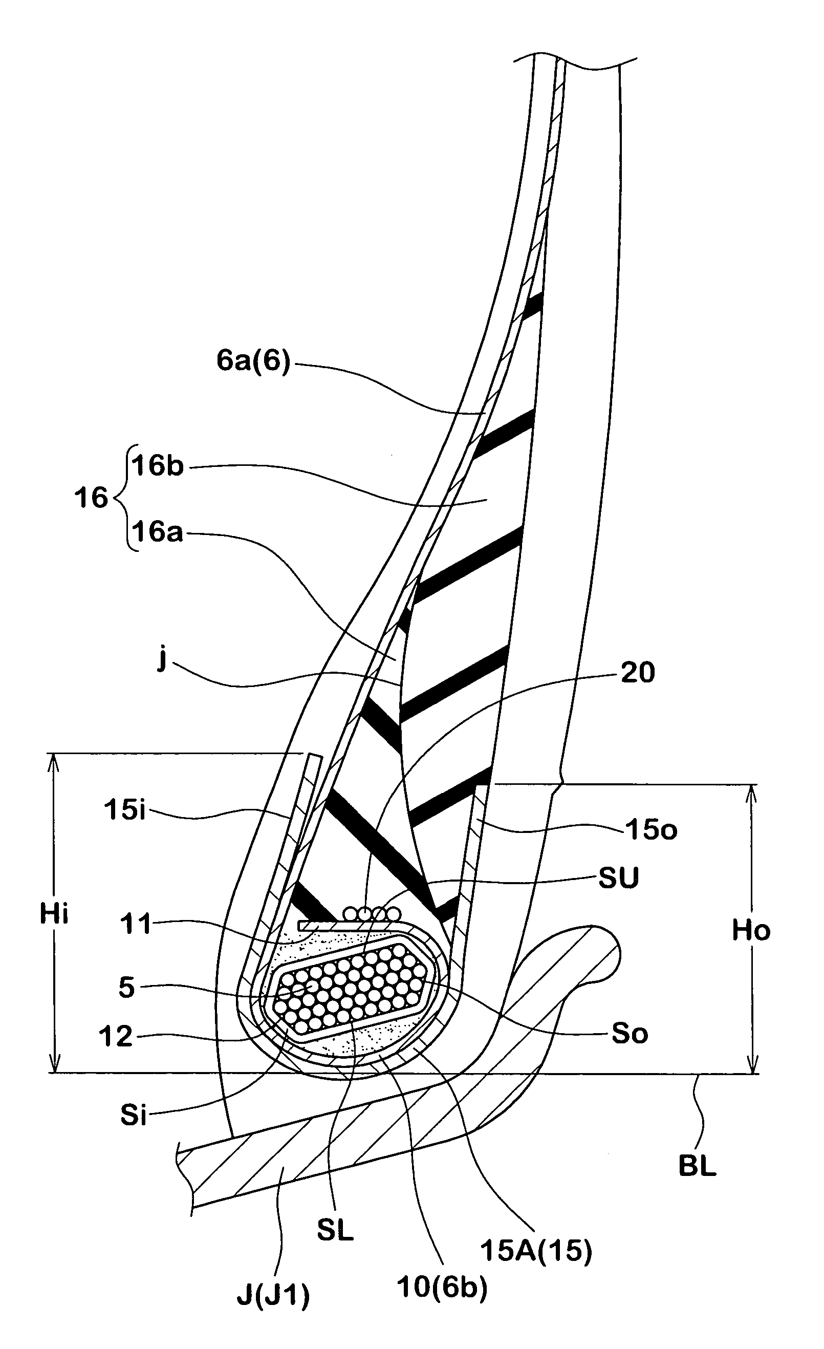
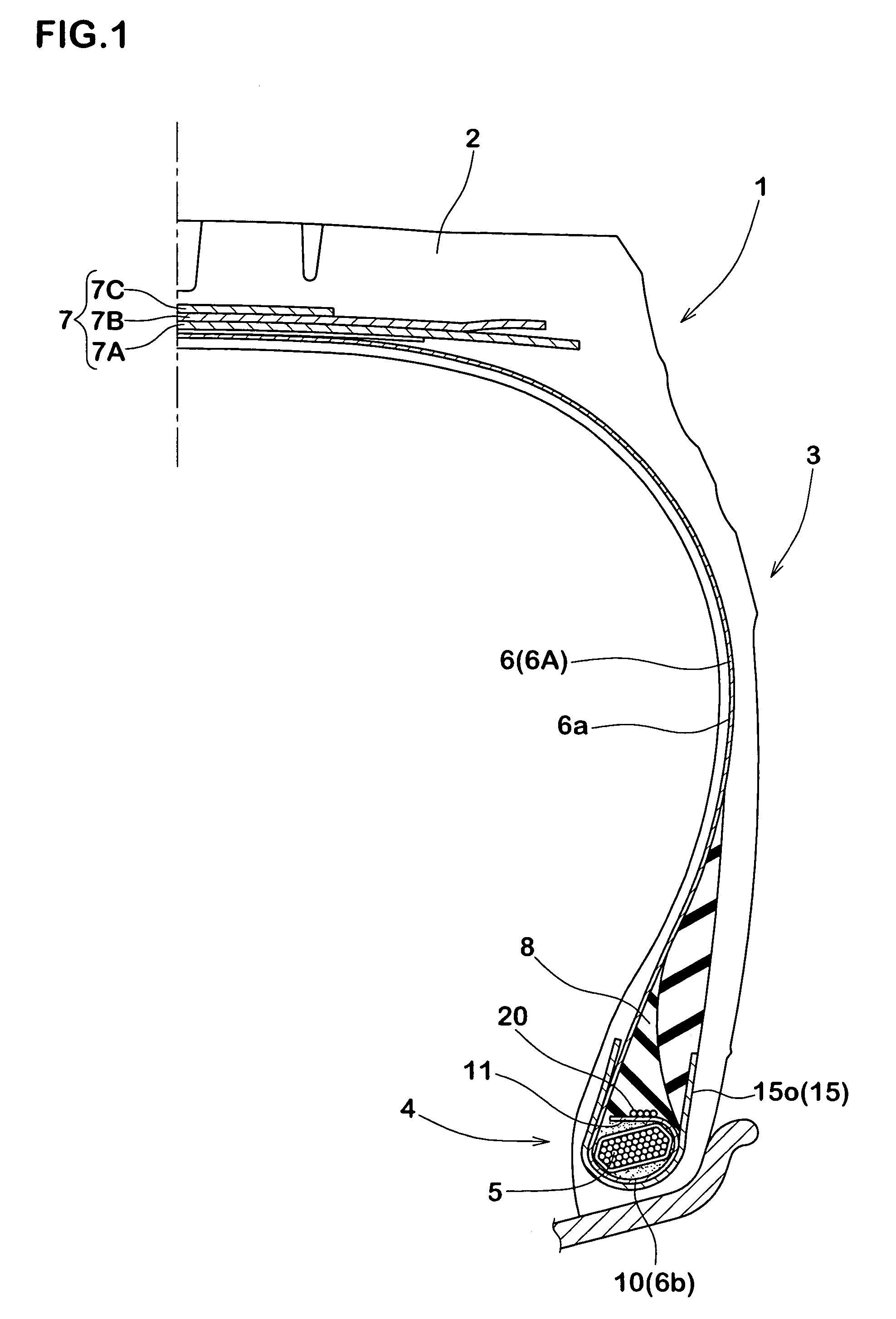
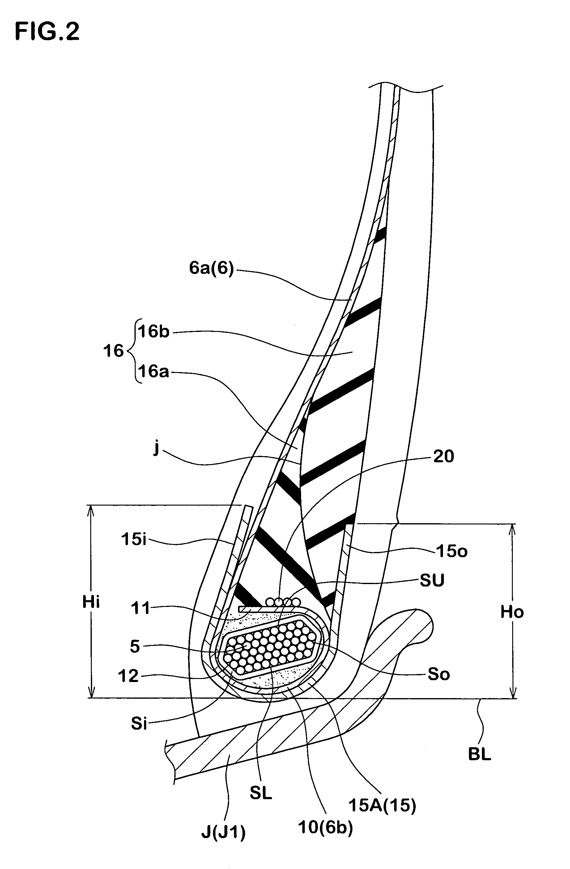
[0105]Heavy duty tires having a tire size of 11R22.5 and the basic structure of FIGS. 1-3 were manufactured according to specifications of Table 1 whereupon the bead durability of the respective sample tires were measured and compared with each other. Specifications other than those of Table 1 were common to all.

[0106]In this respect, the Comparative Example 1 had a structure as illustrated in FIG. 9(A) in which the ply turnup portions of the carcass were wound along outer surfaces of the bead apex rubber. A height h of the ply turnup portions from the bead base line was defined to be 37 mm.

(1) Bead Durability

[0107] General Bead Durability:

[0108]A drum tester was employed and tires were made to run at a velocity of 20 km / h under the following conditions for the rim (7.50×22.5), the internal pressure (700 kPa) and the load (26.72kN×3), and driving times until damages were caused at the bead portion were measured. Evaluations are indicated as indices with the driving time of the Compa...

example 2

[0113]Heavy duty tires (tire size 11R22.5) having the basic structure of FIGS. 1 and 2 and FIG. 5 specifications of Table 2 were manufactured on trial, and bead durability and core deformation was evaluated. Specifications other than those described in Table 2 are operationally identical.

(1) Bead Durability:

[0114]A drum tester was employed and tires were made to run at a velocity of 20 km / h under the following conditions for the rim (7.50×22.5), the standard internal pressure (700 kPa) and thrice the standard load (27.25kN×3), and driving times until damages were caused at the bead portion were measured. Evaluations are indicated as indices with the driving time of the Comparative Example 1 being defined as 100. The larger the values are, the more favorable they are.

(2) Core Deformation:

[0115]The tires were disassembled after performing the durability test for observing presence / absence of deformation of the bead cores such as alignment shift or alignment collapse of the bead wire.

(...


PUM


Abstract

The present invention relates to a heavy duty tire being capable of preventing positional shift of carcass cords in the blowout direction while restricting rupture of the carcass cords for improving bead durability. A ply turnup portions 6b of a carcass 6 includes a sub-portion 11 that extends proximate of an upper surface SU of a bead core 5 in a tire radial direction upon inclining towards a ply main body portion 6a and further includes an auxiliary cord layer 20 for pressing the sub-portion outside thereof in the radial direction. A bead portion 4 is further provided with a U-shaped bead reinforcing layer 15. A periphery of the bead core 5 is coated by a reinforcing rubber layer 15 made of high elastic rubber having a complex elastic modulus E*a of 20 to 70 MPa, and a rubber thickness T0 of a clearance portion G at which bead wires 5w and carcass cords 20 are adjacent is defined to be not less than 0.7 mm while a cushion rubber layer 16 made of low elastic rubber layer 16 is interposed between the reinforcing rubber layer 15 and the carcass cords 20.

Description

BACKGROUND OF THE INVENTION[0001]1. Field of the Invention[0002]The present invention relates to a heavy duty tire in which bead durability is improved by restricting blowout of carcass cords while also restricting deformation of bead cores at bead portions of bead-wind structure.[0003]2. Description of the Related Art[0004]A carcass ply a that constitutes a framework of a tire is generally arranged, as illustrated in FIG. 9(A), in that it is engaged by providing turnup portions a2 which are turned over around the bead cores b, on both sides of a ply main body portion a1 that bridges between bead cores b, b. For the purpose of improvements such as weight saving of the bead cores, it has been recently suggested a structure as disclosed in Japanese Published Patent Application No. 11-321244 of a heavy duty tire employing a carcass ply a constituted from steel cords in which, as illustrated in FIG. 9(B), ply turnup portions a2 are continuously formed at the ply main body portion a1 in ...

Claims


Application Information

Patent Timeline
Patent Type & Authority Patents(United States)
IPC IPC(8): B60C15/00B60C15/06
CPCB60C15/0027B60C15/04Y10T152/10837Y10T152/10819Y10T152/10846B60C2015/044B60C15/0607
Inventor MARUOKA, KIYOTO
Owner SUMITOMO RUBBER IND LTD
Why Eureka
Try Eureka