Headrest device

a headrest and headrest technology, applied in the direction of chairs, pedestrian/occupant safety arrangements, vehicular safety arrangements, etc., can solve the problems of the head of the occupant not being supported, the load applied at the rear-end collision cannot be supported

Inactive Publication Date: 2009-04-14
AISIN SEIKI KK +2
View PDF19 Cites 57 Cited by
  • Summary
  • Abstract
  • Description
  • Claims
  • Application Information

AI Technical Summary

Problems solved by technology

This considerable load can rotate the motor in reverse, which leads to a risk that the load applied at the rear-end collision cannot be supported, that is, the head of the occupant cannot be supported.

Method used


Image

  • Headrest device
  • Headrest device
  • Headrest device

Examples


Embodiment Construction

[0021]One embodiment of the present invention will be explained with reference to illustrations of drawing figures as follows.

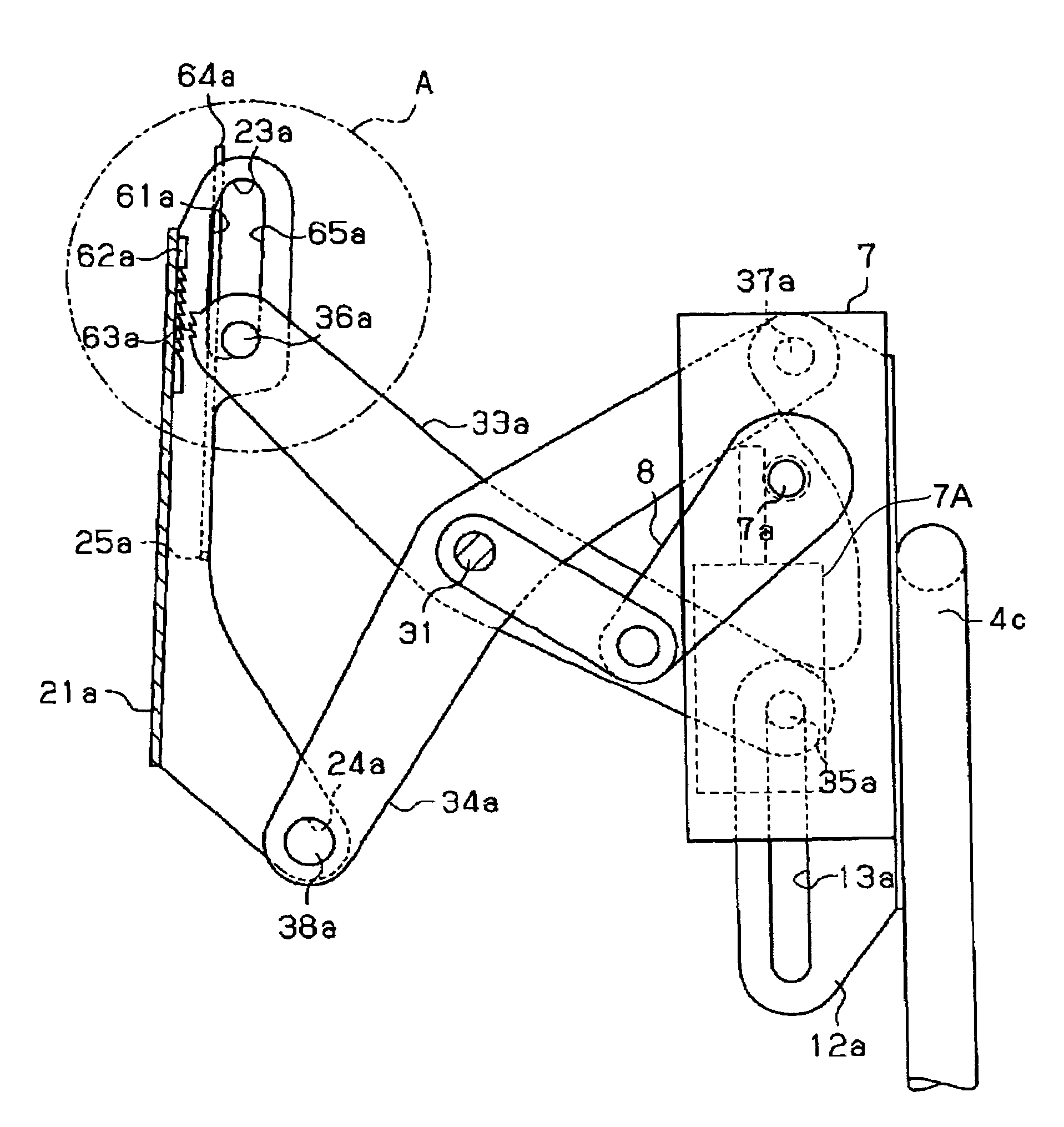
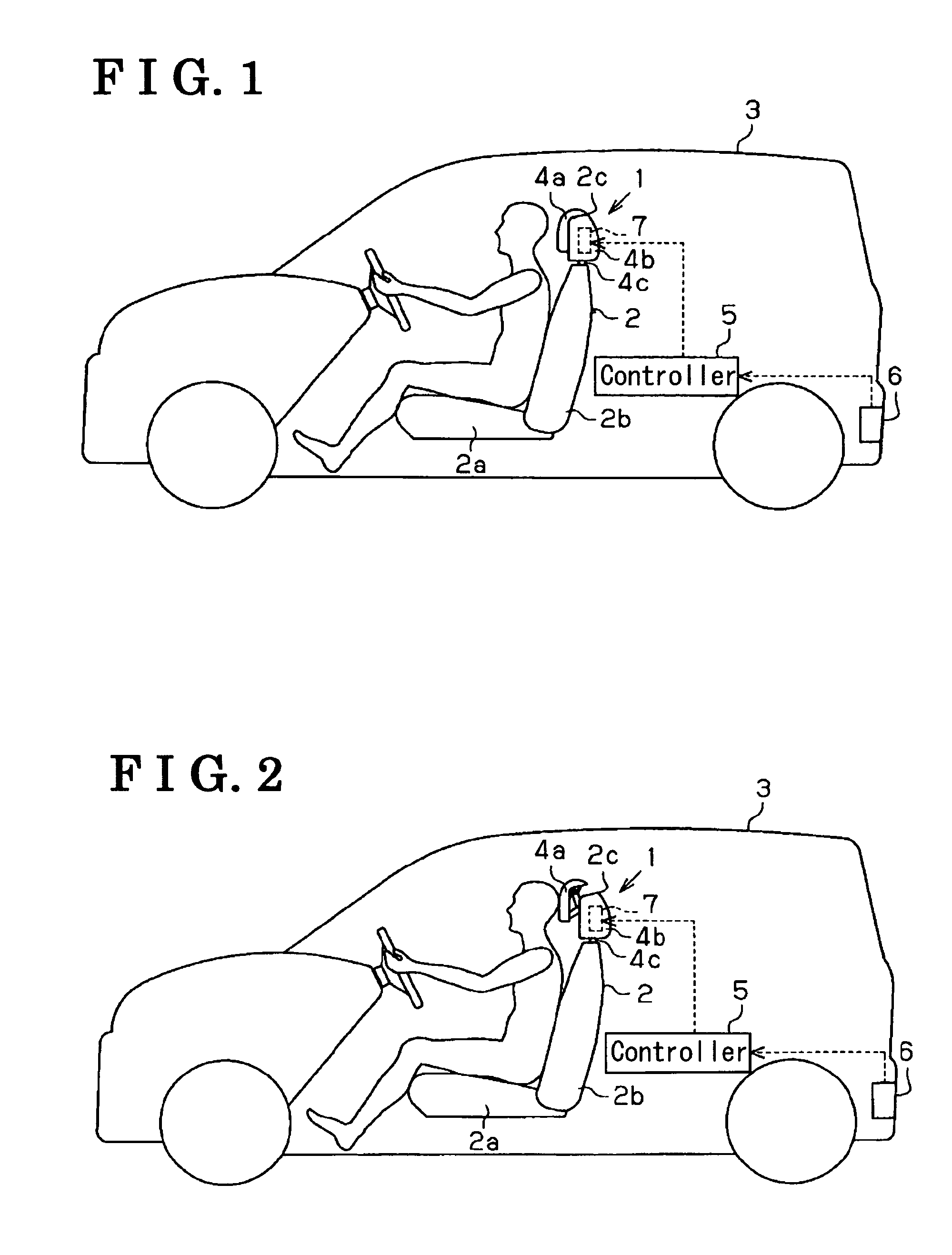
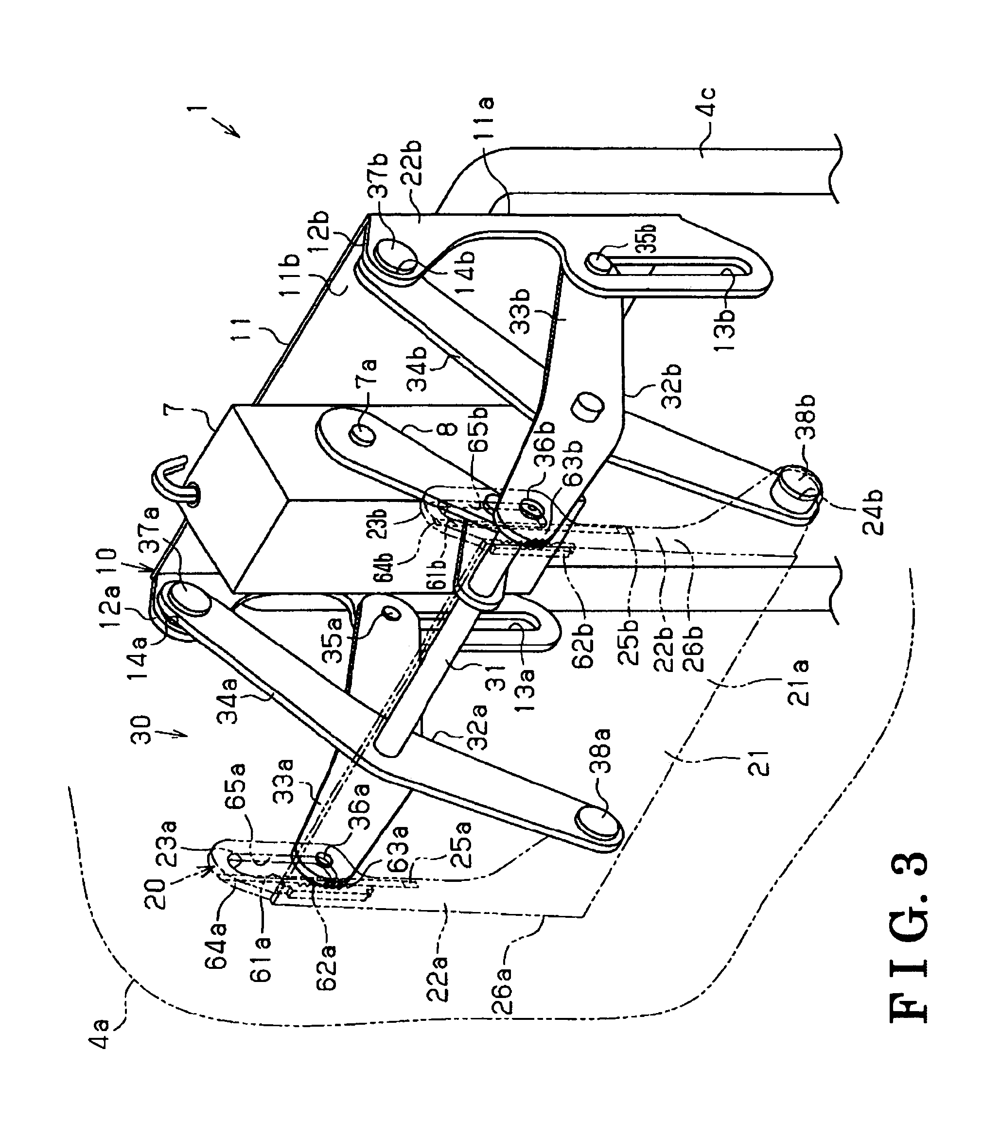
[0022]As shown in FIGS. 1-2, a vehicle 3 is provided with a seat 2 for a vehicle. The seat 2 for the vehicle includes a seat cushion 2a maintained in a vehicle compartment, a seatback 2b supported at a rear end of the seat cushion 2a so as to rotate in a longitudinal direction of the vehicle (i.e., right-left direction in FIG. 1), and a headrest 2c supported by the seatback 2b. The headrest 2c includes a headrest device 1 which forms a part of a frame of the headrest 2c. The headrest 1 is housed in a space formed between a front cover 4a which forms a front side of the headrest 2c and a rear cover 4b which forms a rear side of the headrest 2c, and is supported by a headrest stay 4c provided at a top end portion of the seatback 2b to be positioned at a top part of the seat back 2b.

[0023]The headrest device 1 is connected to a controller 5, and a detection sig...


PUM


Abstract

A headrest device includes a fixed base, a movable base disposed forward relative to the fixed base, at least one first link being rotatably supported by a connecting shaft provided between the movable base and the fixed base, at least one second link being supported by the connecting shaft so as to rotate relative to the first link, a connection portion connecting the movable base and the fixed base to be relatively movable by a relative rotation between the first link and the second link, a drive portion relatively rotating the first link and the second link in a direction so as to deploy the movable base away from the fixed base on the basis of a detected result by a rear-end collision detection means, and at least one relative rotation restricting portion provided for restricting a relative rotation between the first link and the second link about the connecting shaft.

Description

CROSS REFERENCE TO RELATED APPLICATIONS[0001]This application is based on and claims priority under 35 U.S.C. §119 with respect to Japanese Patent Application No. 2005-302194 filed on Oct. 17, 2005, the entire content of which is incorporated herein by reference.FIELD OF THE INVENTION[0002]The present invention relates to a headrest device.BACKGROUND[0003]A headrest device is mounted on a vehicle, which a headrest device mitigates an impact applied to a cervix by restricting a backward movement of a head of an occupant after moving forward when the vehicle is rear-ended or when that the vehicle is to be rear-ended is predicted.[0004]For example, a headrest device described in JPH11-334439A (FIG. 2) includes a drive motor provided in a headrest, a worm fixed to a rotational shaft of the drive motor, and a gear that is engaged with the worm. The drive motor is activated by signals transmitted from a sensor which is mounted on a vehicle to predict or detect rear-end collision. With thi...

Claims


Application Information

Patent Timeline
Patent Type & Authority Patents(United States)
IPC IPC(8): A47C7/38
CPCB60N2/4228B60N2/4885B60N2/888
Inventor TERADA, TAKAMIYAMADA, YUKIFUMIMIZUNO, TAKUYATANIGUCHI, HIROMIMORI, MASATOSHIMATSUBAYASHI, KIYOKAAKAIKE, FUMITOSHINISHIMURA, SEIYA
Owner AISIN SEIKI KK
Why Eureka
Try Eureka