Automatically adjusted electric vehicle staged automatic emergency braking control system

An automatic emergency braking and control system technology, applied in electric braking systems, electric vehicles, brakes, etc., can solve problems such as rear-end collisions, passenger comfort effects, and collisions, and achieve the effect of preventing wheels from locking

Active Publication Date: 2019-11-12
JILIN UNIV
View PDF4 Cites 39 Cited by
  • Summary
  • Abstract
  • Description
  • Claims
  • Application Information

AI Technical Summary

Problems solved by technology

[0005] 1. The current control algorithm of the vehicle-mounted AEB system usually chooses to directly stop the vehicle at the maximum braking deceleration when AEB intervention is required, which will seriously affect the comfort of the members, and emergency braking at high speeds Moving is also prone to dangers such as rear-end collisions
[0006] 2. The AEB system control algorithm does not include the function of road surface information recognition. The algorithm only considers the structural parameters of the vehicle and its own kinematic parameters when designing the algorithm. In order to consider the impact of different roads on the implementation effect of the AEB algorithm
[0007] 3. The control algorithm of the AEB system is not adaptive to changes in road conditions. For example, when the vehicle is driving on a road with a low adhesion coefficient, the maximum braking deceleration of the vehicle may not reach the preset value of the AEB system due to the decrease of the adhesion coefficient. , resulting in a collision; when the vehicle is driving on a road with a certain slope, the slope resistance will cause the actual braking force of the vehicle to change. If the AEB algorithm is not adjusted according to the road slope, it may cause the vehicle to go uphill prematurely. Deceleration creates mistrust for the driver or insufficient deceleration for a downhill vehicle leads to a collision
[0008] 4. For an electric vehicle equipped with a partially decoupled or non-decoupled electric power-assisted braking system, when the AEB system is triggered and starts to apply braking force to the vehicle, due to the presence of Mechanical connection, so the brake pedal will automatically move under the drive of the booster motor. On the one hand, it may cause discomfort and panic to the driver. On the other hand, since the brake pedal is no longer When the braking force is greater, the time for the driver to move his foot to the brake pedal will be longer than usual. This time difference may cause the driver to hesitate or make a wrong operation, resulting in insufficient braking force and danger.

Method used


Image

  • Automatically adjusted electric vehicle staged automatic emergency braking control system
  • Automatically adjusted electric vehicle staged automatic emergency braking control system
  • Automatically adjusted electric vehicle staged automatic emergency braking control system

Examples


Embodiment Construction

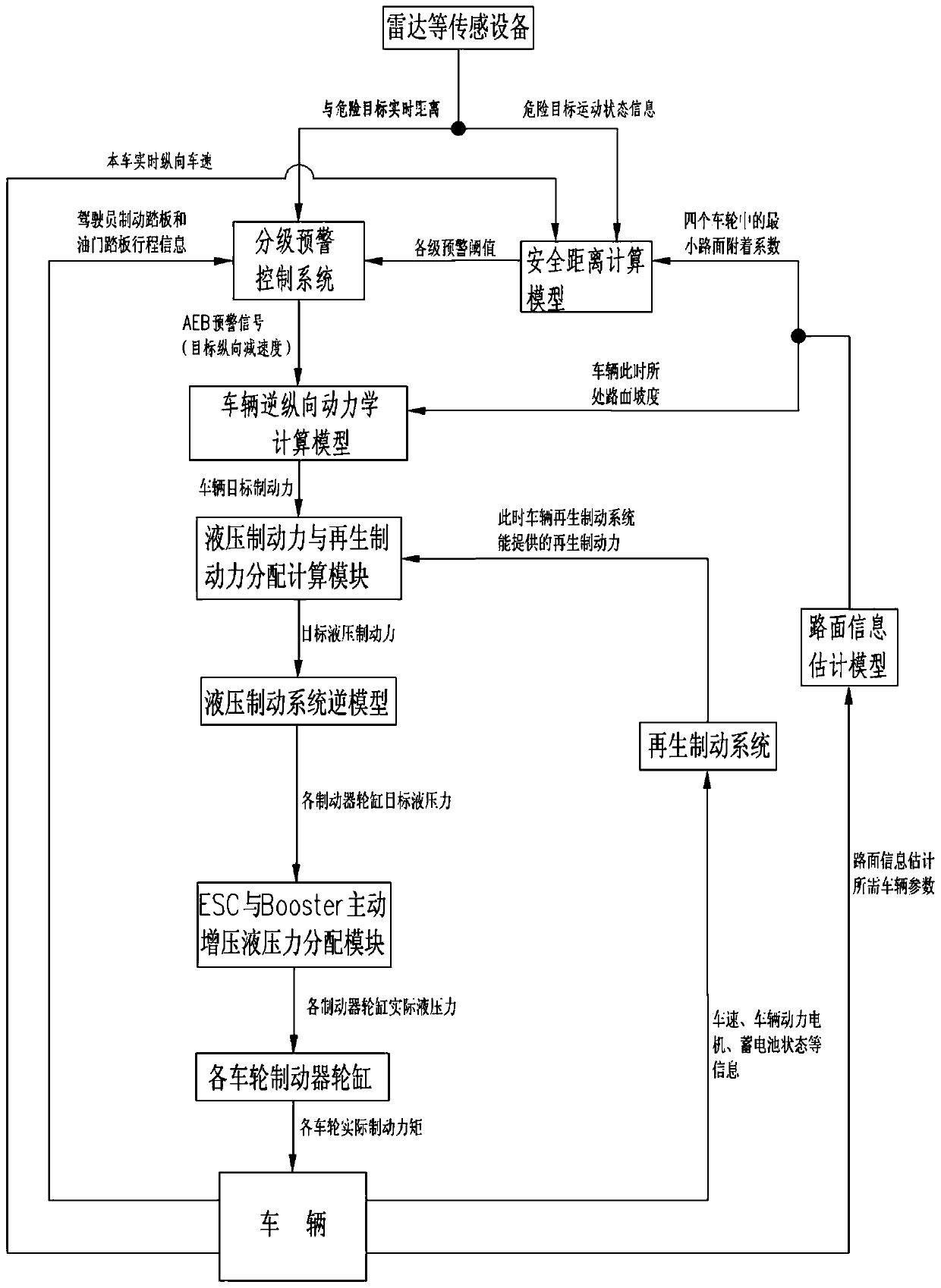
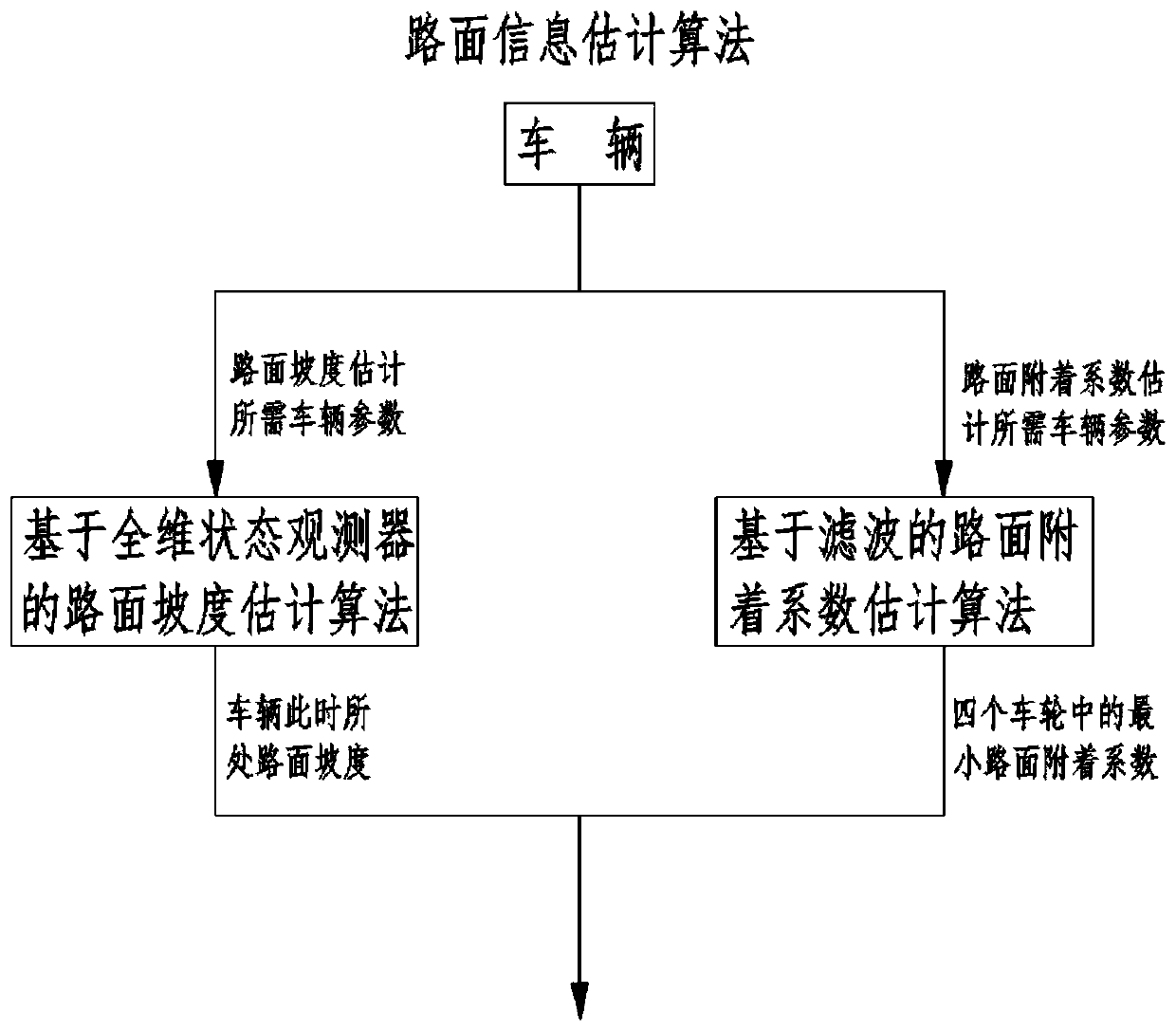
[0040] Please refer to the attached Figure 1-10 According to the present invention, a self-adjusting hierarchical automatic emergency braking control system for an electric vehicle includes: a vehicle-mounted ranging and speed measuring sensor device, a hierarchical early warning control system, a safety distance calculation model, a vehicle inverse longitudinal dynamics calculation model, a hydraulic brake The power and regenerative braking force distribution calculation module, the inverse model of the hydraulic braking system, the ESC and Booster active supercharging hydraulic pressure distribution module, and the road surface information estimation model. The control method of the system is as follows:

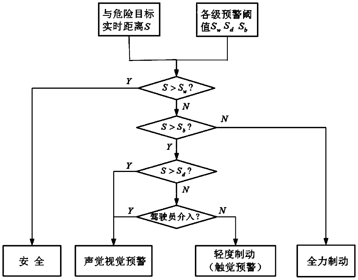
[0041] (1) See attached figure 2 , when the vehicle is running, the vehicle-mounted ranging and speed-measuring sensor equipment transmits the real-time distance S between the vehicle and the dangerous target to the hierarchical early warning control system, and transmit...


PUM


Abstract

The invention relates to an automatically adjusted electric vehicle staged automatic emergency braking control system. The automatically adjusted electric vehicle staged automatic emergency braking control system comprises vehicle-mounted distance measuring and speed measuring sensor equipment, a staged pre-warning control system, a safety distance calculation model, a vehicle reverse longitudinaldynamic calculation model, a hydraulic braking force and regenerative braking force distribution and calculation module, a hydraulic braking system reverse model, an ESC and Booster active pressurizing hydraulic pressure distribution module and a pavement information estimation module; potential safety hazards such as rear-end collision of a rear vehicle caused by great sudden deceleration of a vehicle are reduced while the comfort during triggering an AEB system is improved; by estimating information, such as gradients and adhesion coefficients, of a current running road and a front road ofthe vehicle and controlling online adjusting of parameters, the adapting degree of the AEB system to different pavement statuses is enhanced, the braking energy is sufficiently recycled, the endurancemileage is increased, and the advantages of a vehicle body stability control system ESC and an electronic mechanical braking booster in active pressurizing are sufficiently developed.

Description

technical field [0001] The invention relates to an automatic emergency braking control system for an electric vehicle, in particular to an automatically adjusted hierarchical automatic emergency braking control system for an electric vehicle. Background technique [0002] In recent years, with the continuous development of global automobile technology, the number of automobiles has continued to increase, and vehicle traffic accidents have also increased. In order to reduce the number of road traffic accidents, various automotive active safety technologies and passive safety technologies have been developed rapidly. As an important automotive active safety technology, the Automatic Emergency Brake System (AEB, hereinafter referred to as AEB) can effectively avoid a large number of traffic accidents, and has gradually become a standard configuration of vehicles. [0003] The AEB system is mainly composed of three parts: information collection, control system and actuator. In...

Claims


Application Information

Patent Timeline
Patent Type & Authority Applications(China)
IPC IPC(8): B60T13/74B60W30/09B60W50/14B60W40/06B60W40/064B60W40/076B60L7/10B60W30/02
CPCB60L7/10B60T13/74B60W30/02B60W30/09B60W40/06B60W40/064B60W40/076B60W50/14B60W2050/143
Inventor 赵健宋东鉴朱冰赵文博孙卓王春迪
Owner JILIN UNIV
Why Eureka
Try Eureka