Vehicle headrest apparatus

a headrest and vehicle technology, applied in the direction of vehicular safety arrangements, chairs, pedestrian/occupant safety arrangements, etc., can solve the problems of imposing a severe stress on the ears of passengers, inability to immediately respond, and insufficient movement of the headrest unit, so as to reduce the effect of head restrain

Active Publication Date: 2006-05-23
NISSAN MOTOR CO LTD
View PDF15 Cites 41 Cited by
  • Summary
  • Abstract
  • Description
  • Claims
  • Application Information

AI Technical Summary

Benefits of technology

[0007]It has been discovered that in seatbacks that actuate the headrest using the inertia force of the seated passenger, the headrest unit does not begin moving forward until the rearward displacement of the passenger is large. Consequently, the head rest unit cannot be moved sufficiently forward during the period immedia...

Problems solved by technology

Consequently, the head rest unit cannot be moved sufficiently forward during the period immediately after the collision (when the amount of displace...

Method used


Image

  • Vehicle headrest apparatus
  • Vehicle headrest apparatus
  • Vehicle headrest apparatus

Examples


first embodiment

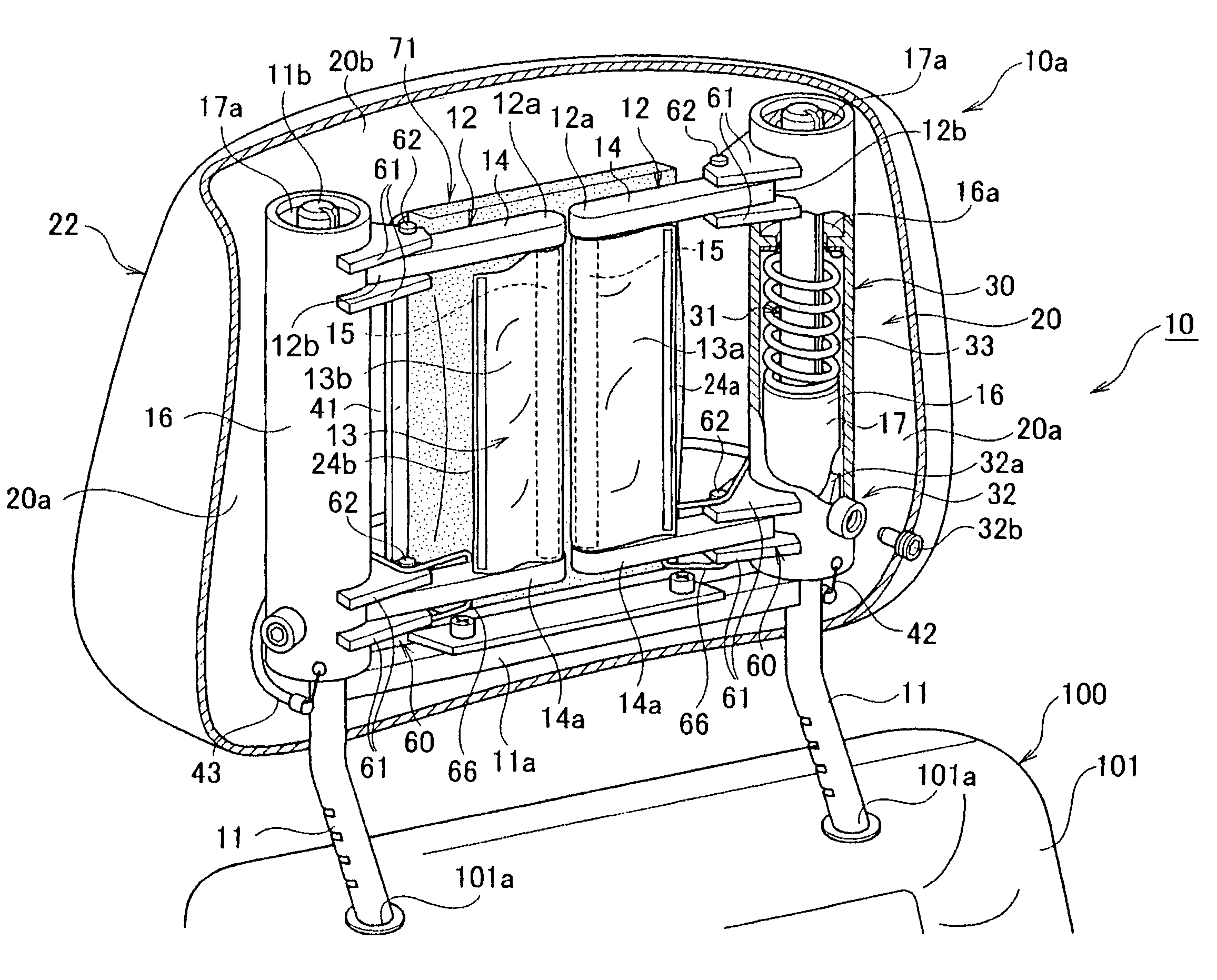
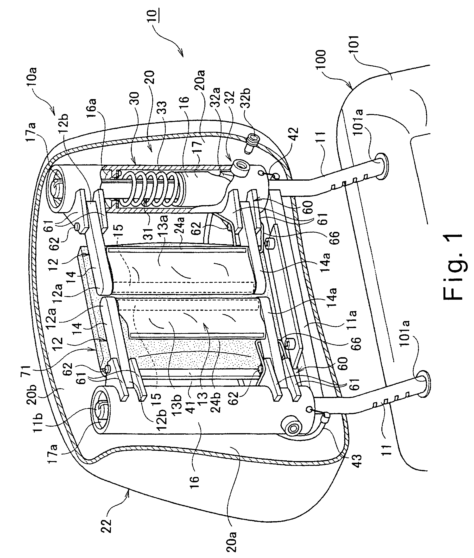
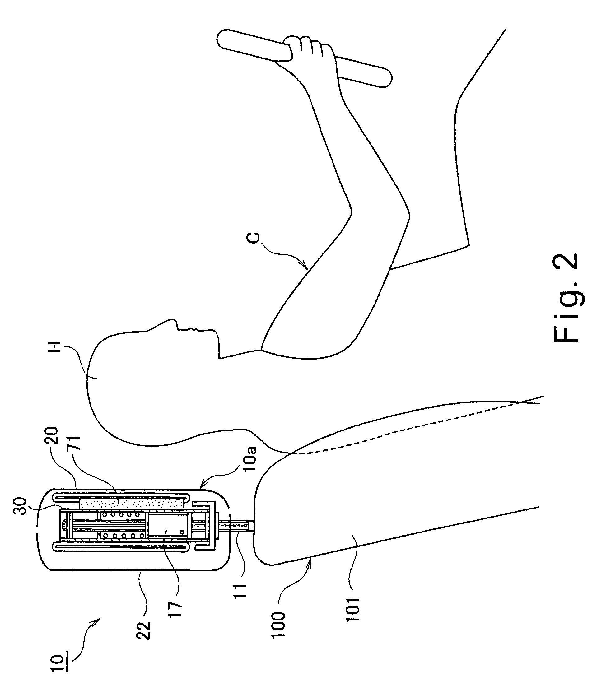
[0034]Referring initially to FIGS. 1 to 11, the vehicle headrest apparatus 10 is illustrated in accordance with a first embodiment of the present invention. FIG. 1 is a front perspective view of a headrest unit 10a in an initial state. FIG. 1 is a front perspective view of a headrest unit 10a when headrest unit 10a is in the initial state with the portions removed for purposes of illustration. FIG. 2 is a simplified schematic side elevational view of the mounted state of the headrest unit 10a. FIG. 3 is an exploded front perspective view of the headrest unit 10a. FIG. 4 is a simplified, exploded rear perspective view of the headrest unit 10a (selected portions being transparent for purposes of illustration) in its extended or deployed state.

[0035]As shown in FIGS. 1 to 4, the headrest unit 10a of this embodiment includes a mounting member comprising a pair of stays 11. The vehicle headrest apparatus 10 is adjustably coupled to a vehicle seat 100 by the stays 11. More specifically, t...

second embodiment

[0106]Referring now to FIG. 13, a vehicle headrest apparatus in accordance with a second embodiment will now be explained. FIG. 13 is a rear perspective view of a modified front cover 20′ with a soft form body 71′ in the form of a piece of urethane 71′ in its natural or undeformed state. Basically, in this embodiment, the cover 20′ with the soft foam body 71′ is substituted for the cover and the soft foam body 71′ of the first embodiment. In view of the similarity between the first and second embodiments, the parts of the second embodiment that are identical to the parts of the first embodiment will be given the same reference numerals as the parts of the first embodiment. Moreover, the descriptions of the parts of the second embodiment that are identical to the parts of the first embodiment may be omitted for the sake of brevity. The parts of the second embodiment that differ from the parts of the first embodiment will be indicated with a prime (′).

[0107]In the second embodiment, a...

third embodiment

[0110]Referring now to FIGS. 14 and 15, a vehicle headrest apparatus in accordance with a third embodiment will now be explained. In view of the similarity between the first and third embodiments, the parts of the third embodiment that are identical to the parts of the first embodiment will be given the same reference numerals as the parts of the first embodiment. Moreover, the descriptions of the parts of the third embodiment that are identical to the parts of the first embodiment may be omitted for the sake of brevity.

[0111]FIG. 14 is a see-through perspective view of the headrest unit with the left and right headrest members 12 in the initial state. FIG. 15 is a see-through perspective view of the headrest unit with the left and right headrest members in the deployed state. In the third embodiment, as shown in FIG. 14, an elastic member 73 serving as an auxiliary swing force adding device is provided such that it spans across the left and right headrest members 12 between the lef...


PUM


Abstract

A vehicle headrest apparatus has a headrest unit mounted to an upper end of a seatback. The headrest unit has a headrest members with a head restraining member configured to be tensioned to restrain a passenger's head upon a rear-end collision. The headrest unit quickly and reliably restrains a seated passenger's head during a rear-end collision without utilizing the inertia force of the passenger's body by detecting the rear-end collision and pushing the headrest unit only outward in the forward direction of the vehicle. The headrest unit also has a swing/pushup device that to pushes the headrest members upwardly and forwardly. An auxiliary swing force adding device applies an auxiliary spring force in the deployment direction of the headrest members to increase the deployment speed of the headrest members and shorten the amount of time required to achieve initial contact between the passenger's head H and the head restraining member.

Description

BACKGROUND OF THE INVENTION[0001]1. Field of the Invention[0002]The present invention generally relates to a vehicle headrest apparatus that is used on a vehicle seat and supports the head of a seated passenger. More specifically, the present invention relates to a vehicle headrest apparatus that is configured to reliably restrain a passenger's head and suppress the rearward movement of a passenger's head when a rear-end collision occurs by actuating a headrest unit itself.[0003]2. Background Information[0004]Many conventional automobile seatbacks are designed to protect the head of a seated passenger in the event of a rear-end collision. In one example of such an arrangement, the seatback bears the dynamic load that acts on a seated passenger due to inertia when the vehicle is subjected to a rear-end collision. The movement of a member in the seatback that is displaced as a result of the dynamic load is transmitted to a headrest support arm and the headrest unit moves toward the fr...

Claims


Application Information

Patent Timeline
IPC IPC(8): B60N2/427B60N2/48B60R21/00B60N2/42
CPCB60N2/4279B60N2/4885B60N2/4864B60N2002/022B60N2/865B60N2/888
Inventor PAL, CHINMOYKOBAYASHI, IZUMI
Owner NISSAN MOTOR CO LTD
Why Eureka
Try Eureka