Electric power distribution device
a technology of power distribution device and power supply, which is applied in the direction of windings, dynamo-electric components, electric cable installations, etc., can solve the problems of increasing cost, increasing manpower and production costs, and increasing processing man-hours
- Summary
- Abstract
- Description
- Claims
- Application Information
AI Technical Summary
Benefits of technology
Problems solved by technology
Method used
Image
Examples
first embodiment
[0040]A first embodiment of an electric power distribution device according to the present invention will be described with reference to Figures.
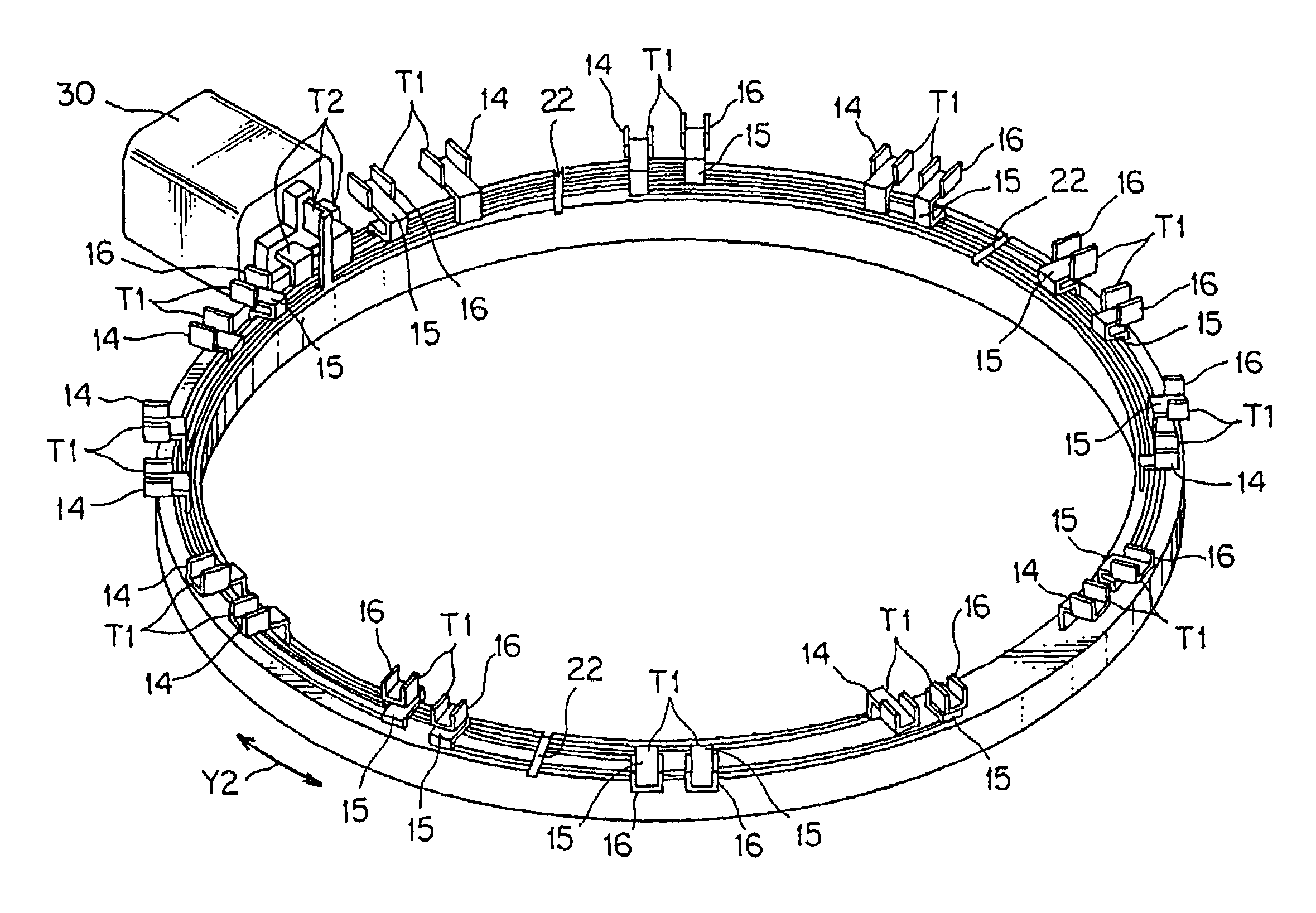
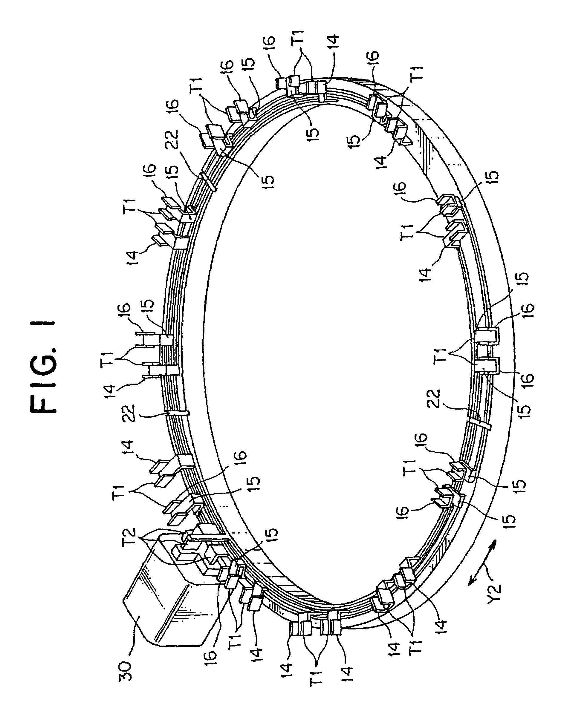
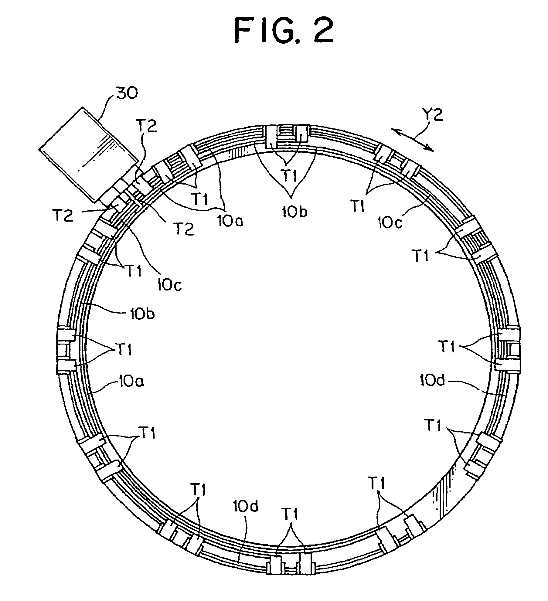
[0041]A brushless motor (not shown) generally includes a rotor connected directly with a motor rotation shaft, and a ring-shaped stator surrounding the rotor. Three-phase stator coils are wound around cores of the stator. The stator coils are arranged on a circle about the motor rotation shaft. In this embodiment, for example, twelve stator coils are wound around cores, and arranged at equal intervals on the circle about the motor rotation shaft. The electric power distribution device of the present invention is used for supplying electric power by connecting the stator coils L as shown in FIG. 8.
[0042]As shown in FIGS. 1 and 2, the electric power distribution device includes a plurality of band-shaped bus bars 10a to 10d (shown in FIG. 2), on which end coil terminals T1 are formed in a width direction Y1 for supplying electric power to the...
second embodiment
[0065]Next, a second embodiment according to the present invention will be explained.
[0066]As shown in FIGS. 10 to 12, the electric power distribution device includes band-shaped bus bars 10a to 10d each in which the coil terminal T1 is formed on an end in the width direction Y1, and a insulating holder 20 on which receiving grooves 21e to 21f are formed. The coil terminal T1 supplies power to the stator coil L. The receiving grooves 21e to 21f receive the bus bars 10a to 10d in a manner that they are insulated from each other.
[0067]The coil terminal T1 and the power terminal T2 in the second embodiment respectively work the same as those in the first embodiment. As shown in FIG. 12, a plurality of flat parts 11 are formed on the band-shaped bus bars 10a to 10d, and a folded part 18 is interposed between the flat parts 11 adjacent to each other. In the band-shaped bus bars 10a to 10d, lengths L1 at the flat parts 11 except at both ends are equal to each other. Folding angles θ of th...
PUM
 Abstract
Description
Claims
Application Information
 - R&D
- Intellectual Property
- Life Sciences
- Materials
- Tech Scout
- Unparalleled Data Quality
- Higher Quality Content
- 60% Fewer Hallucinations
Browse by: Latest US Patents, China's latest patents, Technical Efficacy Thesaurus, Application Domain, Technology Topic, Popular Technical Reports.
© 2025 PatSnap. All rights reserved.Legal|Privacy policy|Modern Slavery Act Transparency Statement|Sitemap|About US| Contact US: help@patsnap.com


