
Earphone detection circuit

a detection circuit and earphone technology, applied in the direction of stereophonic circuit arrangements, electrical transducers, transmission, etc., can solve the problems of reducing the overall volume occupation of the capacitor, and achieve the effect of reducing the overall volume occupation of the circuit, facilitating the attachment of the earphone detection circuit, and reducing the overall dimensions of the earphone driving circui

Inactive Publication Date: 2009-04-14
HTC CORP
View PDF4 Cites 18 Cited by
  • Summary
  • Abstract
  • Description
  • Claims
  • Application Information

AI Technical Summary

Benefits of technology

The solution effectively reduces the overall dimensions of the earphone driving circuit while maintaining automatic audio signal switching capabilities, enabling accurate detection of earphone presence / absence and efficient audio signal routing.

Problems solved by technology

Although the circuit module having this rearrangement may produce a circuit with an inferior resistor-capacitor effect, the elimination of the capacitor reduces overall volume occupation of the circuit.

Method used


Image

  • Earphone detection circuit
  • Earphone detection circuit
  • Earphone detection circuit

Examples


Embodiment Construction

[0023]Reference will now be made in detail to the present preferred embodiments of the invention, examples of which are illustrated in the accompanying drawings. Wherever possible, the same reference numbers are used in the drawings and the description to refer to the same or like parts.

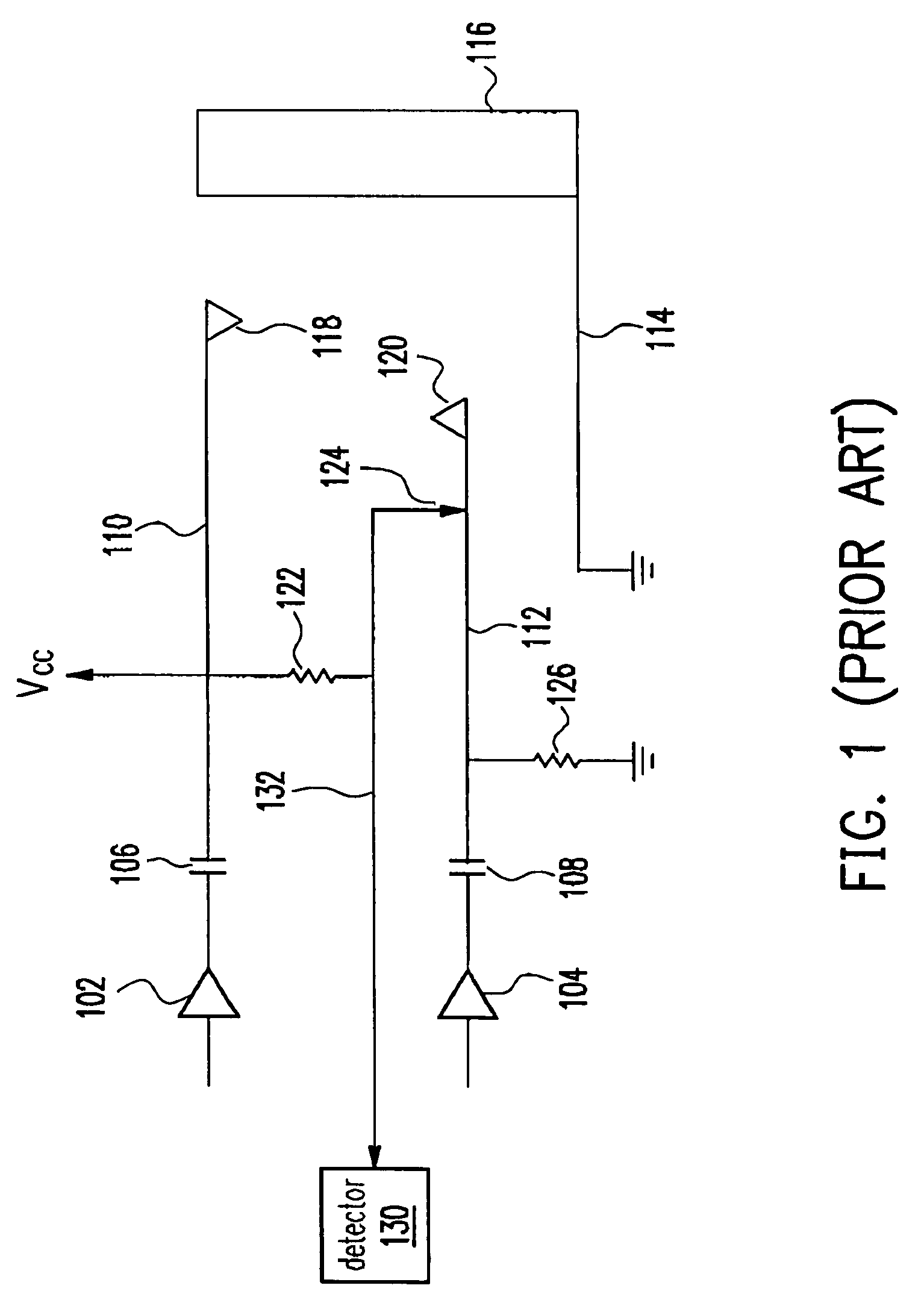
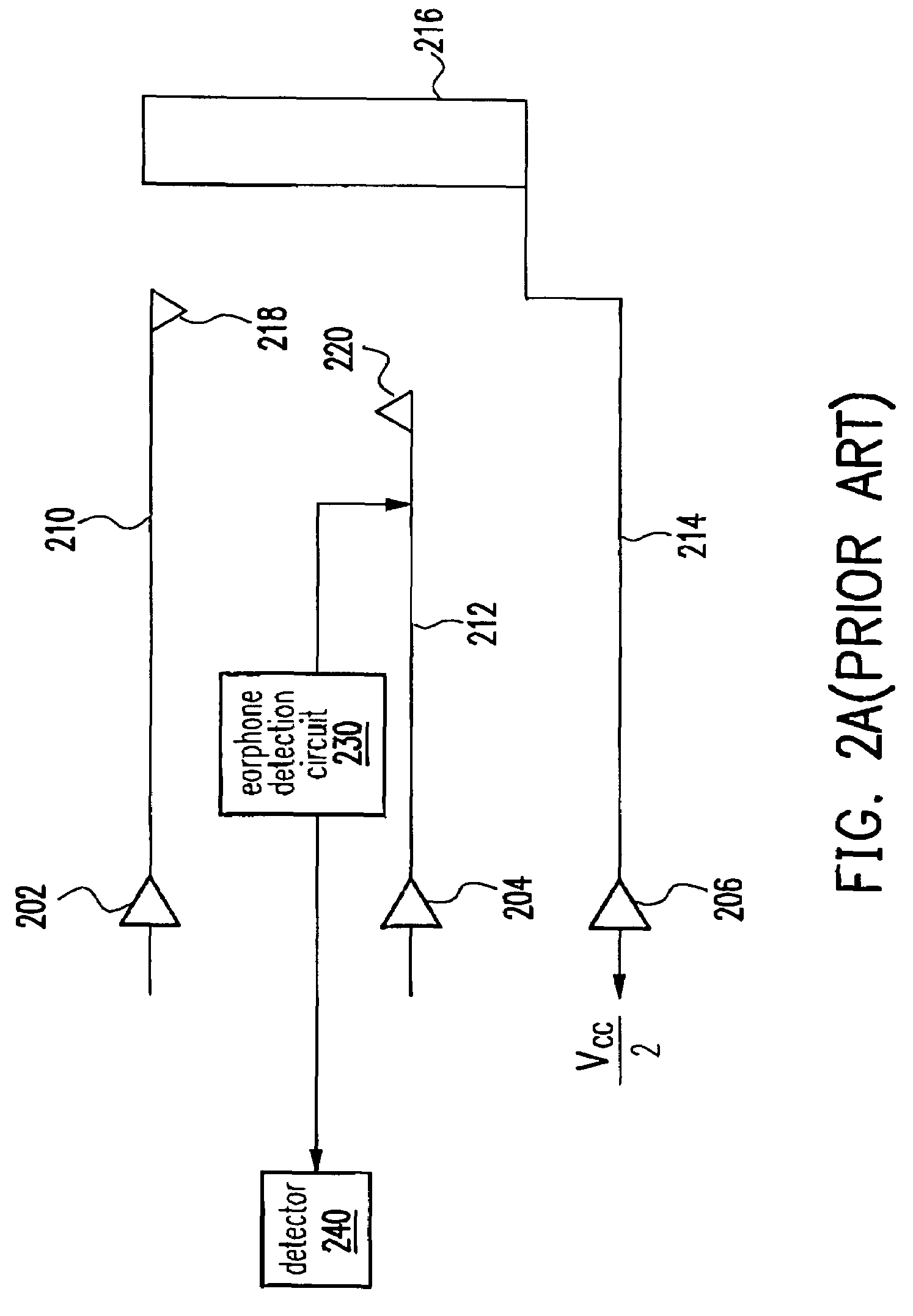
[0024]To familiarize the innovation in this invention, a conventional earphone driving circuit is briefly introduced with reference to FIG. 2A. In FIG. 2A, the earphone driving circuit has no actual ground connection. The earphone driving circuit is connected to a virtual ground line 214 having a virtual ground voltage of about Vcc / 2. When the portion including the resistors 122 and 126 and the detection line 132 as shown in FIG. 1 is used as an earphone detection circuit 230, the entire circuit is shown in FIG. 2B. Note that the elements in FIG. 2B identical to the ones shown in FIGS. 1 and 2A are labeled identically.

[0025]As shown in FIG. 2B, the audio signal transmission line 212 is at a voltage V...


PUM


Abstract

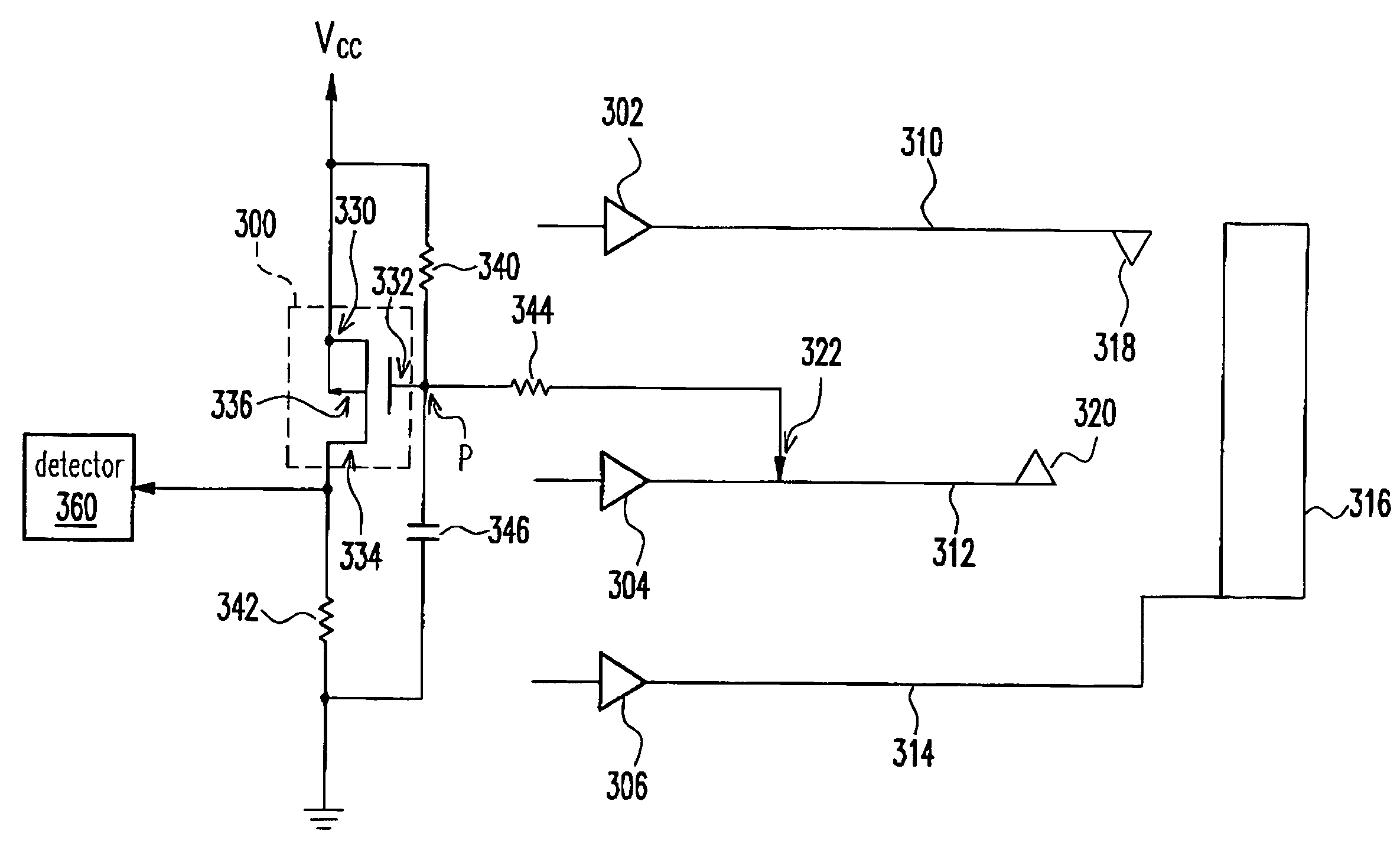
An earphone detection circuit that comprises a transistor, a first resistor, a second resistor, a third resistor and a detector. The transistor has a first terminal, a second terminal, a third terminal and a fourth terminal. The first and the fourth terminal of the transistor are electrically connected to an operating voltage. One end of the first resistor is electrically connected to the first terminal of the transistor and the other end of the first resistor is electrically connected to the second terminal of the transistor. One end of the second resistor is electrically connected to the third terminal of the transistor and the other end is electrically connected to a ground terminal. One end of the third resistor is electrically connected to the second terminal of the transistor and the other end is electrically connected to the detection terminal of an earphone driving circuit. One end of a capacitor is electrically connected to the second terminal of the transistor and the other end is electrically connected to the ground terminal. The detector is electrically connected to the third terminal of the transistor.

Description

CROSS REFERENCE TO RELATED APPLICATIONS[0001]This application claims the priority benefit of Taiwan application serial no. 91102578, filed Feb. 15, 2002.BACKGROUND OF INVENTION[0002]1. Field of Invention[0003]The present invention relates to an earphone detection circuit. More particularly, the present invention relates to an earphone detection circuit without a common ground terminal for left and right audio channel.[0004]2. Description of Related Art[0005]At present, most audio signal providers such as audio recorders, camcorders, televisions or portable computers have two major audio output channels. Aside from having a built-in speaker, these audio signal providers also have a socket for plugging an earplug so that people may listen through an earphone. In addition, these audio signal providers have an automatic detector inside for switching the audio attendance mode automatically. In other words, audio signals are channeled to the earphone or other externally plugged device onc...

Claims


Application Information

Patent Timeline
Patent Type & Authority Patents(United States)
IPC IPC(8): H04R1/10H04R29/00
CPCH04R5/04H04R2420/05
Inventor LIANG, CHAN-LI
Owner HTC CORP
Learn More