
Variable capactor structure and method of manufacture

a variable capacitor and capactor technology, applied in the direction of diodes, semiconductor devices, electrical apparatus, etc., can solve the problems of affecting the resistance it is difficult to achieve further improvement in the operating efficiency of the variable capacitor, so as to achieve the effect of small resistan

Inactive Publication Date: 2005-01-27
UNITED MICROELECTRONICS CORP
View PDF2 Cites 6 Cited by
  • Summary
  • Abstract
  • Description
  • Claims
  • Application Information

AI Technical Summary

Benefits of technology

[0010] Accordingly, one object of the present invention is to provide a variable capacitor or varactor having a considerably smaller resistance.
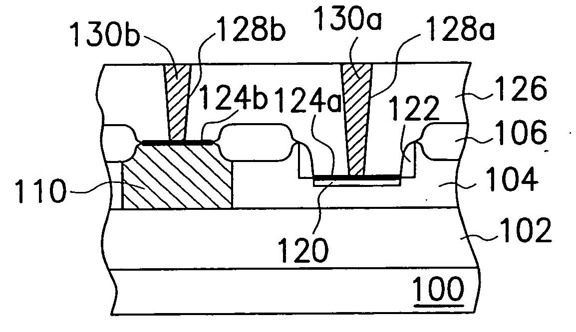
[0016] In this invention, resistance of the variable capacitor is reduced by shortening the overall width of the second type ion-doped well from the second type ion-doped region to the first type ion-doped buried layer.
[0017] In the manufacturing step for producing the variable capacitor, a portion of the process is carried out in tandem with the process for fabricating the bipolar devices. Hence, resistance of the variable capacitor is reduced without increasing mask requirements.
[0018] Unlike a conventional variable capacitor that requires a deep collector, contacts are directly used to make contact with the buried layer so that resistance of the variable capacitor is further reduced.
[0019] Furthermore, the doped region is formed at the bottom section of the shallow trench isolation structure to reduce overall volume occupation of the circuit layout.

Problems solved by technology

However, in a conventional variable capacitor structure, the resistance of the variable capacitor is largely affected by the high resistance of the N-well 14.
Since resistance at the N-well 14 is difficult to reduce, further improvement in the operating efficiency of a variable capacitor is hard to come by.

Method used


Image

  • Variable capactor structure and method of manufacture
  • Variable capactor structure and method of manufacture
  • Variable capactor structure and method of manufacture

Examples


first embodiment

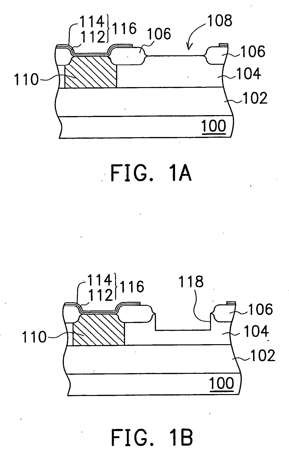
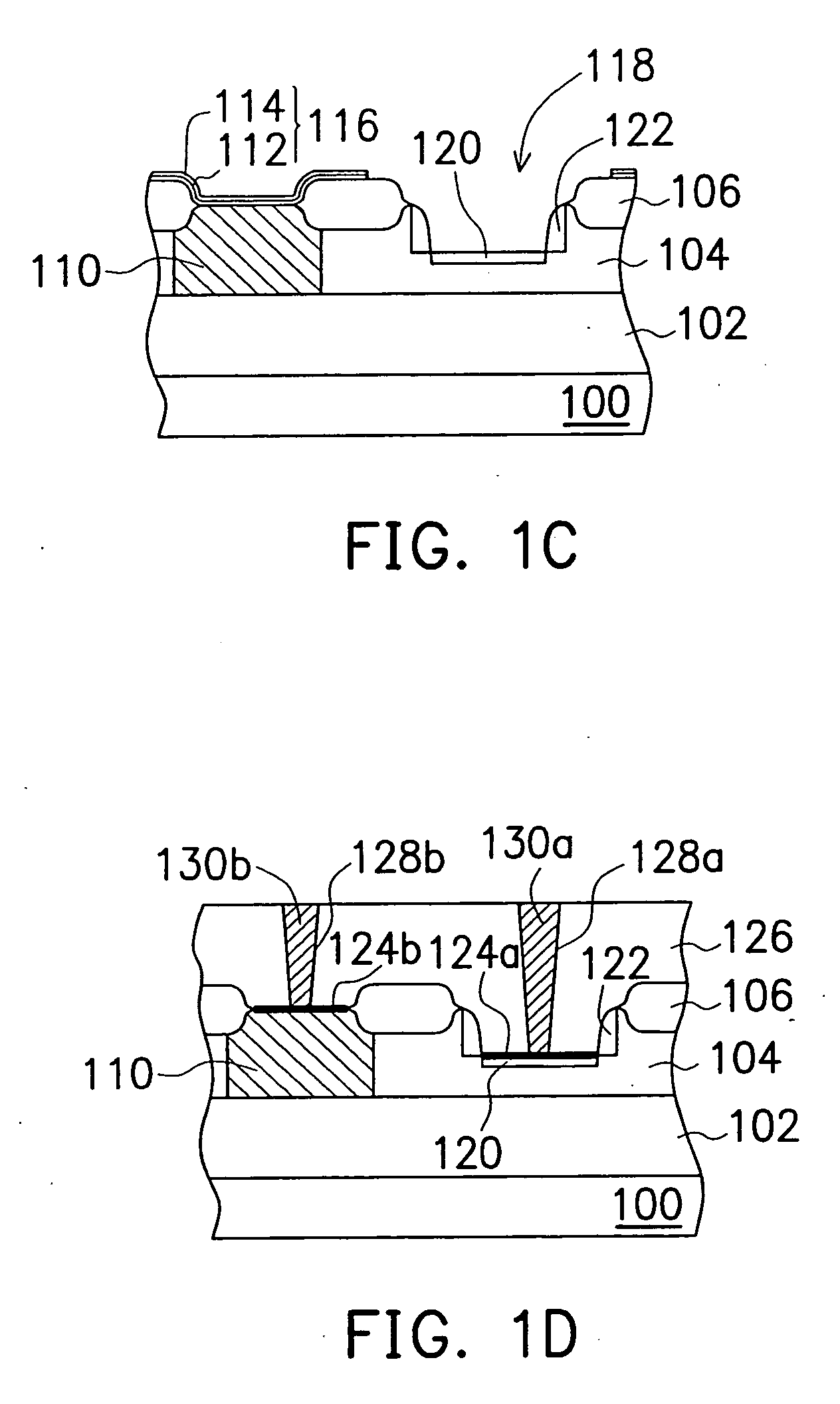
[0037] In the first embodiment, the P+-doped region 120 is formed at the bottom of the opening 118. Hence, the thickness from the P+-doped region 120 to the N+ buried layer 102 is reduced. Ultimately, overall resistance of the variable capacitor decreases considerably.

[0038] In addition, a portion of the fabricating step may combine with the bipolar manufacturing processes. Hence, the total number of masks in manufacturing the variable capacitor in this invention is identical to a conventional process. In other words, the manufacturing process is able to reduce the resistance of a variable capacitor without any increase in the number of required masks.

[0039] Furthermore, the variable capacitor comprises a P+-doped region, a N+ buried layer and a P-type deep collector. However, other arrangements are also possible such as an N+-doped region, a P+ buried layer and an N-type deep collector.

[0040]FIGS. 2A to 2E are schematic cross-sectional views showing the progression of steps for p...

second embodiment

[0049] In the second embodiment, the P+-doped region 212b is formed in the N-well 204 at the bottom of the opening 208b. Hence, the distance from the P+-doped region 212b to the N+ buried layer 202 is reduced. Ultimately, overall resistance of the variable capacitor decreases considerably.

[0050] Furthermore, a portion of the fabricating step may combine with the bipolar manufacturing processes. Hence, the total number of masks in manufacturing the variable capacitor in this invention is identical to a conventional process. In other words, the manufacturing process is able to reduce the resistance of a variable capacitor without any increase in the number of required masks.

[0051] Although the variable capacitor comprises a P+-doped region and a N+ buried layer, other arrangements are also possible, such as an N+-doped region and a P+ buried layer.

[0052]FIGS. 3A to 3F are schematic cross-sectional views showing the progression of steps for producing a variable capacitor according to...

third embodiment

[0061] In the third embodiment, the initial and final points of the variable capacitor are formed in the same active area. Hence, overall layout area of the capacitor is reduced.

[0062] Unlike a conventional variable capacitor that requires a deep collector to connect with the N+ buried layer, the contacts directly contact with the N+ buried layer. Because the contact is made from low resistant metallic material while a conventional deep collector is made from doped silicon, resistivity of the deep collector is considerably higher than the contact. In this invention, the buried layer 302 is connected through the contact 324b. Consequently, resistance of the variable capacitor is further reduced and the quality factor of the variable capacitor is increased.

[0063] In addition, the P+-doped region 312 is formed in the N-well 304 at the bottom of the opening 308. Hence, the distance from the P+-doped region 312 to the N+ buried layer 302 is reduced. Ultimately, overall resistance of the...


PUM


Abstract

A variable capacitor comprising a substrate having a first type ion-doped buried layer, a first type ion-doped well, a second type ion-doped region and a conductive layer thereon. The first type ion-doped well is formed within the substrate. The first type ion-doped well has a cavity. The first type ion-doped buried layer is in the substrate underneath the first type ion-doped well. The first type ion-doped buried layer and the first type ion-doped well are connected. The second type ion-doped region is at the bottom of the cavity of the first type ion-doped well. The conductive layer is above and in connection with the first type ion-doped buried layer.

Description

CROSS-REFERENCE TO RELATED APPLICATION [0001] This application is a continuation of a prior application Ser. No. 10 / 091,942, filed Mar. 5, 2002.BACKGROUND OF THE INVENTION [0002] 1. Field of Invention [0003] The present invention relates to a variable capacitor (varactor) structure and its method of manufacture. More particularly, the present invention relates to a high-frequency variable capacitor structure and its method of manufacture. [0004] 2. Description of Related Art [0005] In this fast-changing society, wireless communication techniques are progressing at an unbelievably rapid pace and hence play an important role in data communication networks. Wireless communication is mostly conducted at very high frequency. Amongst the components used in high-frequency communication, variable capacitor (varactor for short) occupies a center stage. [0006] In general, to change the capacitance of a variable capacitor, supply voltage to the variable capacitor is varied. When the capacitanc...

Claims


Application Information

Patent Timeline
IPC IPC(8): H01L27/08
CPCH01L27/0808
Inventor GAU, JING-HORNGCHEN, ANCHOR
Owner UNITED MICROELECTRONICS CORP
Learn More