
Cable tie having detachable tail

a cable tie and tail technology, applied in the field of cable ties, can solve the problems of not being able to achieve the same rating of the unslitted cable tie, the method is not suitable for one-piece cable ties, and the technology is not readily transferable to one-piece cable ties

Active Publication Date: 2009-04-21
THOMAS & BETTS INT INC
View PDF24 Cites 29 Cited by
  • Summary
  • Abstract
  • Description
  • Claims
  • Application Information

AI Technical Summary

Benefits of technology

Enables easy removal of the excess tail length without tools, maintaining the cable tie's strength and flexibility, and facilitating easier bundling by incorporating slits on surfaces rather than sides.

Problems solved by technology

While this method enables a user to detach a two-piece cable tie tail without using tools, this method is not suitable for one-piece cable ties.
This is because these side slits will significantly reduce the cross-sectional area of the one-piece tie and hence such a side-slitted cable tie cannot attain the same rating as its un-slitted twin.
While this side-slitting method is suitable for two-piece cable ties, such technology is not readily transferable to one piece cable ties.
Thus, the placement of side slits as shown in the '430 patent will compromise the strength of a one-piece cable tie if the slits align with the recess between the teeth.
This is because the slit would further erode the load-bearing cross-sectional area of the tie thereby rendering it only marginally useful.

Method used


Image

  • Cable tie having detachable tail
  • Cable tie having detachable tail
  • Cable tie having detachable tail

Examples


Embodiment Construction

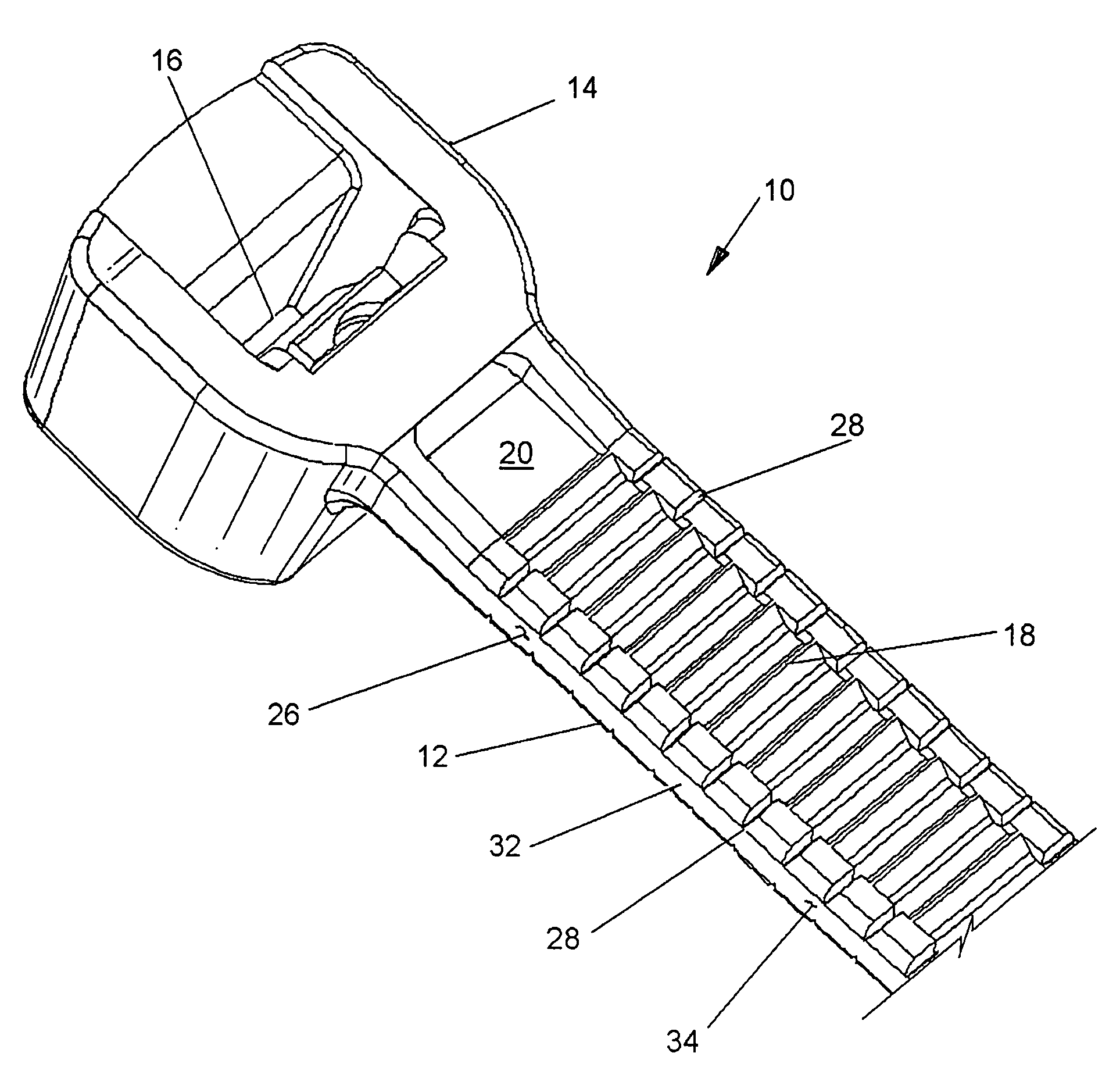
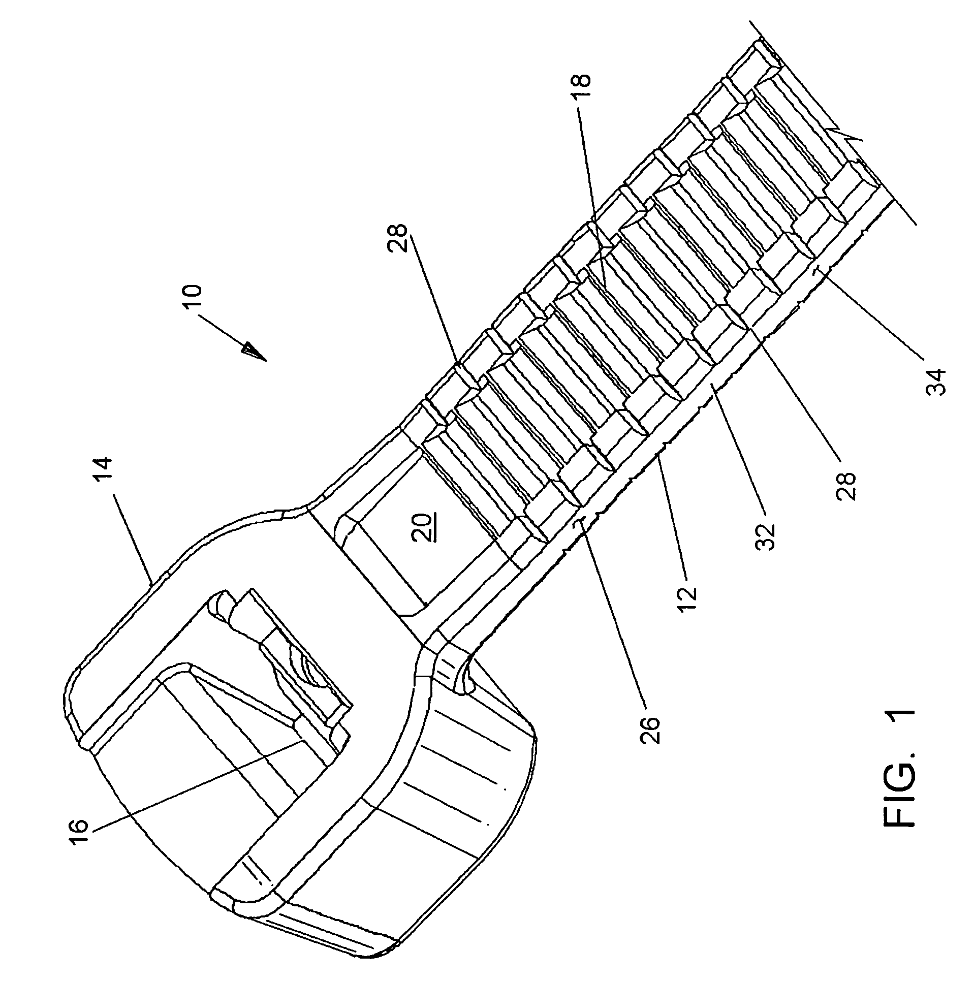
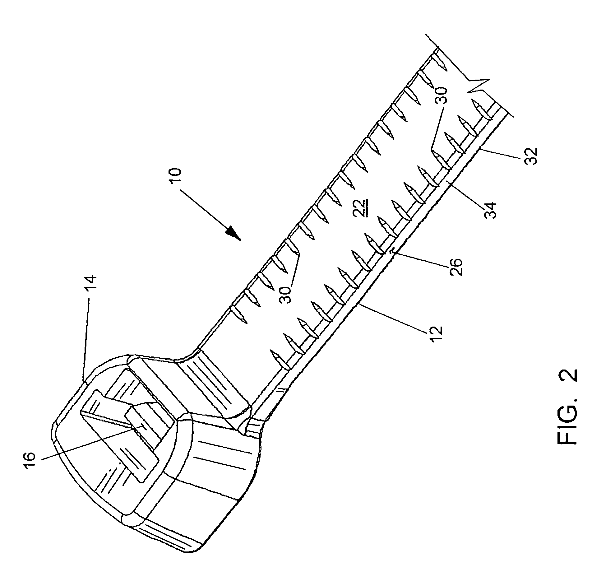
[0020]Referring to the drawings, there is shown one-piece cable tie 10 having a tail 12 forming all or a part of an elongated strap, a head 14 and a flexible pawl 16 all generally made of a suitable plastic material and generally manufactured by an integral molding process.

[0021]The parallel teeth 18 that run along a bottom surface 20 of tail 12 while FIG. 2 illustrates the generally smooth planar top surface 22 of cable tie 10. While such is the preferred embodiment, both sides of tail 12 could be configured with teeth 18 therein if desired.

[0022]Teeth 18 and pawl 16 of this embodiment are specially designed for one-way ratchet-type inter-engagement in order to keep cable tie 10 securely bundled or tensioned about cables and the like as is well known in the art.

[0023]The strap includes recesses 24 intermediate teeth 18. The recesses 24 are evenly spaced and permit a portion of pawl 16 to fit therein and engage one or more surfaces of teeth 18 so as to prevent tail 12 from being pul...


PUM


Abstract

A one-piece cable tie includes a tail which is configured with a plurality of slits or notches therein. These slits are in alignment with the recesses in the tail and extend no deeper than the depth of the recesses. Such slits are designed to aid the use in removing the excess tail from the cable tie once the tie has been tensioned around a bundle. The user first bends the tail so as to close the slits in one side of the tie and then twists the tie about its longitudinal axis so as to separate the excess tail from the tie.

Description

CROSS-REFERENCE TO RELATED APPLICATION[0001]This application claims priority to U.S. Provisional Patent Application No. 60 / 706,404, filed on Aug. 8, 2005, which is incorporated herein by reference.FIELD OF THE INVENTION[0002]The present invention relates generally to cable ties for bundling one or more cables or the like. More particularly, the present invention relates to integrally formed one-piece cable ties which permit the removal of the tail of the tie once bundled.BACKGROUND OF THE INVENTION[0003]Cable ties have long been used to bundle one or more articles such as cables and the like. These ties are typically plastic elongate straps having a tail at one end and a locking head at the other end for receiving the tail. The head includes a locking mechanism in the form of an integrally formed locking pawl (one-piece) or an inserted metallic barb (two-piece).[0004]Both the one-piece and two-piece cable ties operate substantially the same way in that the free end of the tail is lo...

Claims


Application Information

Patent Timeline
Patent Type & Authority Patents(United States)
IPC IPC(8): B65D63/10
CPCB65D63/1063F16L3/2332Y10T24/1498
Inventor LAPORTE, RICHARD
Owner THOMAS & BETTS INT INC
Learn More