Double sided table top display apparatus

a display apparatus and double-sided technology, applied in the field of display devices, can solve the problems of requiring a foot print, affecting the use effect, and deflating during use,

Inactive Publication Date: 2009-04-21
FLAGG RODGER H
View PDF5 Cites 10 Cited by
  • Summary
  • Abstract
  • Description
  • Claims
  • Application Information

AI Technical Summary

Benefits of technology

[0011]The present invention relates to a double sided table top display apparatus having a first double sided upright sub-assembly, a second double sided upright sub-assembly, and upper and lower horizontal cross-members sized to extend between the first and second double sided upright sub-assemblies, to span the desired length of the table top. A flexible sheet material with indicia thereon is releasably secured to the modular table top display apparatus at assembly, and may be rolled up for transport or storage. First and second rotating clamp arms extend beneath the table top to releasably secure respective first and second double sided upright sub-assemblies directly to the table top. Optional lighting may be supported by the rigid frame. The double sided table top display apparatus may be disassembled and compactly stored in a carrying case or bag, for ease of transport and storage.

Problems solved by technology

They are light weight, compact and portable, but require a foot print that takes up hundreds of square inches of the available table area, and are expensive to make.
These also take up substantial table space when erected upon a table, and viewing from the side is partially restricted.
Vertical roll up displays have no means to secure the display to a tabletop, and thus are usually used from the floor and not adapted for securement to a tabletop.
These displays are very compact when deflated, but will deflate during use, if accidentally punctured, and require a large footprint to support the display.
The vendor is often limited in usable display space to a six foot or eight foot long table.
Some trade shows require the vendor's display to be placed only upon the table top, and restrict use of floor mounted displays.

Method used


Image

  • Double sided table top display apparatus
  • Double sided table top display apparatus
  • Double sided table top display apparatus

Examples


Embodiment Construction

)

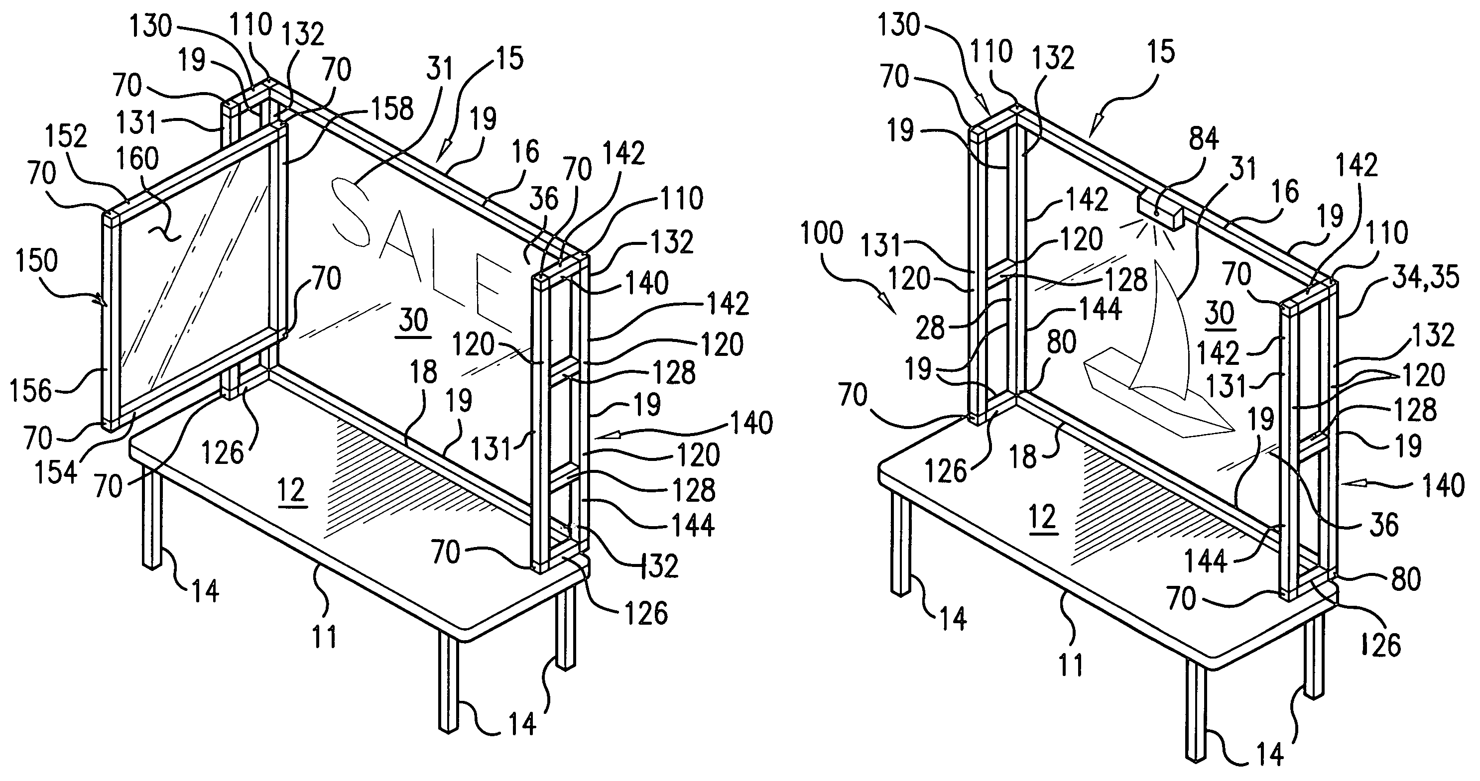
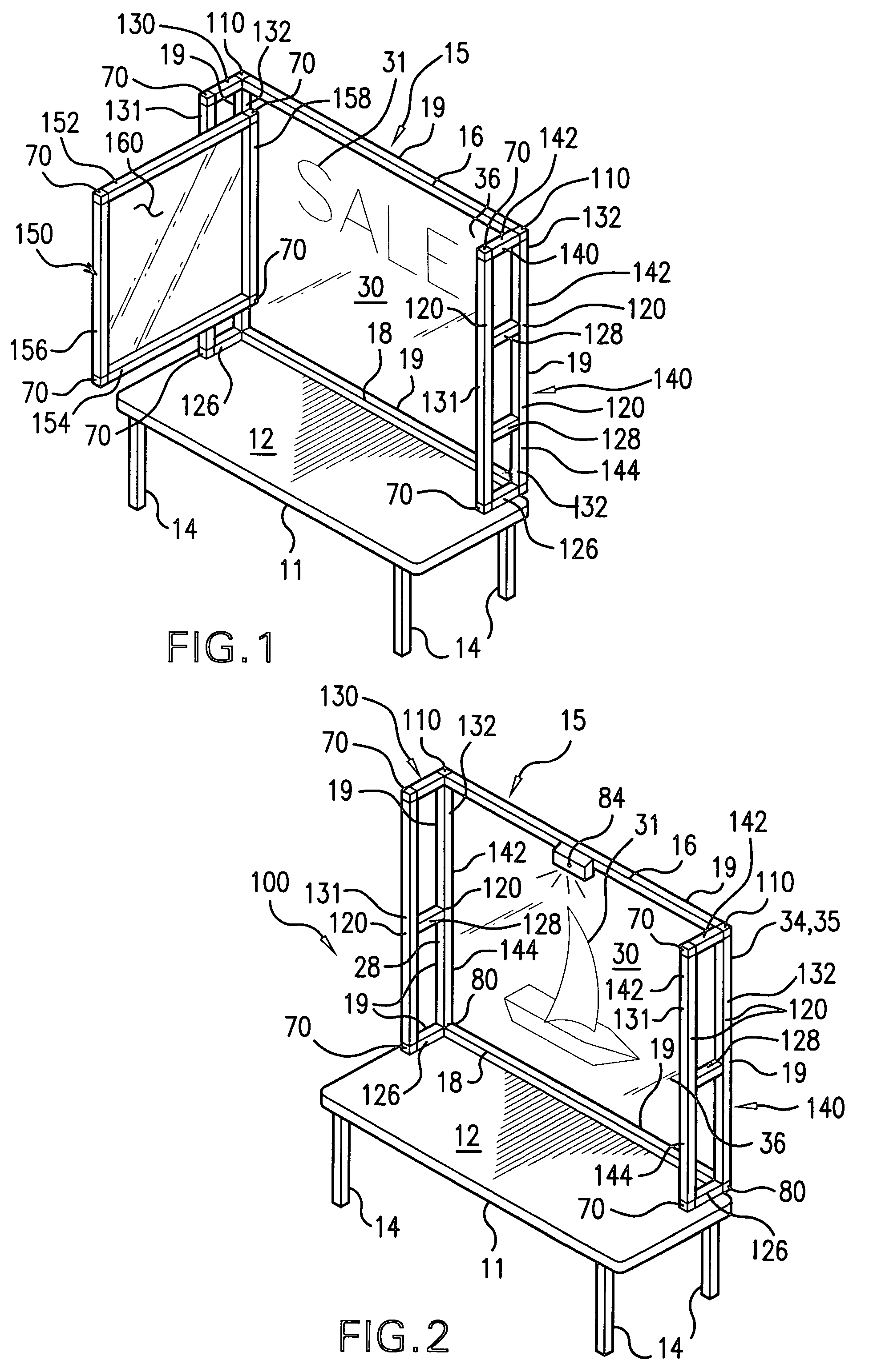
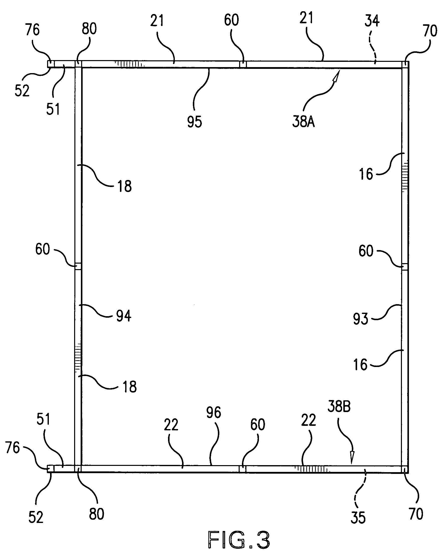
[0031]As shown in FIG. 1 through FIG. 8, the double sided table top display apparatus 100 is easily configured to substantially fit the length of a new or existing table 11, having a table top 12. The frame 15 is made of tubular members 19, which are each preferably square or rectangular in shape, although other shapes, such as round, oblong or multi-sided may alternately be used. The tubular members 19 are preferably made of aluminum for strength and light weight, although other metals or plastics may alternately be used without departing from the scope of this invention, or from the following claims.

[0032]Straight connectors 60, right angle connectors 70, three way connectors 110, tee connectors 120 and four-way connectors 80 are selectively used to connect the double sided table top display apparatus 100 at assembly.

[0033]Upper and lower horizontal cross-members 16, 18 extend between the first double sided upright sub-assembly 130 and the second double sided upright sub-assembly...


PUM


Abstract

A double sided table top display apparatus having a first double sided upright sub-assembly, a second double sided upright sub-assembly, and upper and lower horizontal cross-members, which extend between the first and second double sided upright sub-assemblies, to substantially span the desired length of the table top. A one or more horizontal cross member extension(s) may be selectively used to extend the length of the display apparatus for longer displays. A flexible sheet material with indicia thereon is releasably secured to the modular table top display apparatus at assembly, and may be rolled up for transport or storage. A rotatable clamp extends beneath the table top to secure each of the first and second upright sub-assemblies directly to the table top. Optional lighting may be supported by the rigid frame. The modular table top display apparatus my be disassembled and compactly stored in a carrying case or bag, for ease of transport and storage.

Description

CROSS-REFERENCE TO RELATED TOPICS[0001]This patent application is a continuation-in-part of utility patent application Ser. No. 10 / 673,432 entitled MODULAR TABLE TOP DISPLAY APPARATUS, filed Sep. 30, 2003 now U.S. Pat No. 7,140,134, by Rodger H. Flagg, wherein a Notice of Allowance has been received, and is hereby incorporated by reference herein.STATEMENT REGARDING FEDERALLY SPONSORED RESEARCH[0002]Not Applicable.REFERENCE TO SEQUENCE LISTING A TABLE, OR A COMPUTER PROGRAM LISTING COMPACT DISK APPENDEX[0003]Not Applicable.BACKGROUND OF THE INVENTION[0004]There are many types of display devices known in the art. One popular type of display device is known as the pop-up display. Pop-up displays have been adapted for floor use as well as for table top use. These devices have multiple arms which pivot and expand to support graphics or other indicia. They are light weight, compact and portable, but require a foot print that takes up hundreds of square inches of the available table area,...

Claims


Application Information

Patent Timeline
Patent Type & Authority Patents(United States)
IPC IPC(8): A47B5/00G09F5/02
CPCG09F7/18G09F15/00A47B37/02
Inventor FLAGG, RODGER H.
Owner FLAGG RODGER H
Why Eureka
Try Eureka