EMI gasket

a gasket and emi technology, applied in the direction of electrically conductive connections, basic electric elements, electrical apparatus, etc., can solve the problems of not ensuring a sufficient resistance between the emi gasket and the sheet steel, and demonstrating mechanical damage, so as to minimise the risk of galvanic corrosion and improve the electric contact

Inactive Publication Date: 2007-10-23
CORIANT
View PDF12 Cites 7 Cited by
  • Summary
  • Abstract
  • Description
  • Claims
  • Application Information

AI Technical Summary

Benefits of technology

[0007]The EMI gasket of the invention serves to improve electric contact between a precoated steel cage and rack and a second EMI gasket by the backing surface (contact backing) of the metal EMI gasket and attachment of the contact backing to the precoated sheet steel. The fixed contact backing provides an even surface with the desired length, on which the EMI gasket can be either mounted directly in an electrically conductive manner, or against which mechanical and electric contact can be made by a second EMI gasket.
[0008]The use of an EMI gasket provides conditions for long-term and reliable electric contact, such that is required when forming an interface shielding against electric interference from an electronic casing or rack.
[0010]The differences in the electric potentials of the selected materials are small, given the same basic material of the two members and the very close potentials of zinc coating and iron. This contributes to a minimised risk of galvanic corrosion.

Problems solved by technology

However, the electrically conductive coating mentioned above, which has been provided on precoated sheet steel plates, has proved susceptible to mechanical damage, and in the practice, the electric coating has not ensured sufficiently low resistance between the EMI gasket and the sheet steel.

Method used


Image

  • EMI gasket
  • EMI gasket
  • EMI gasket

Examples


Embodiment Construction

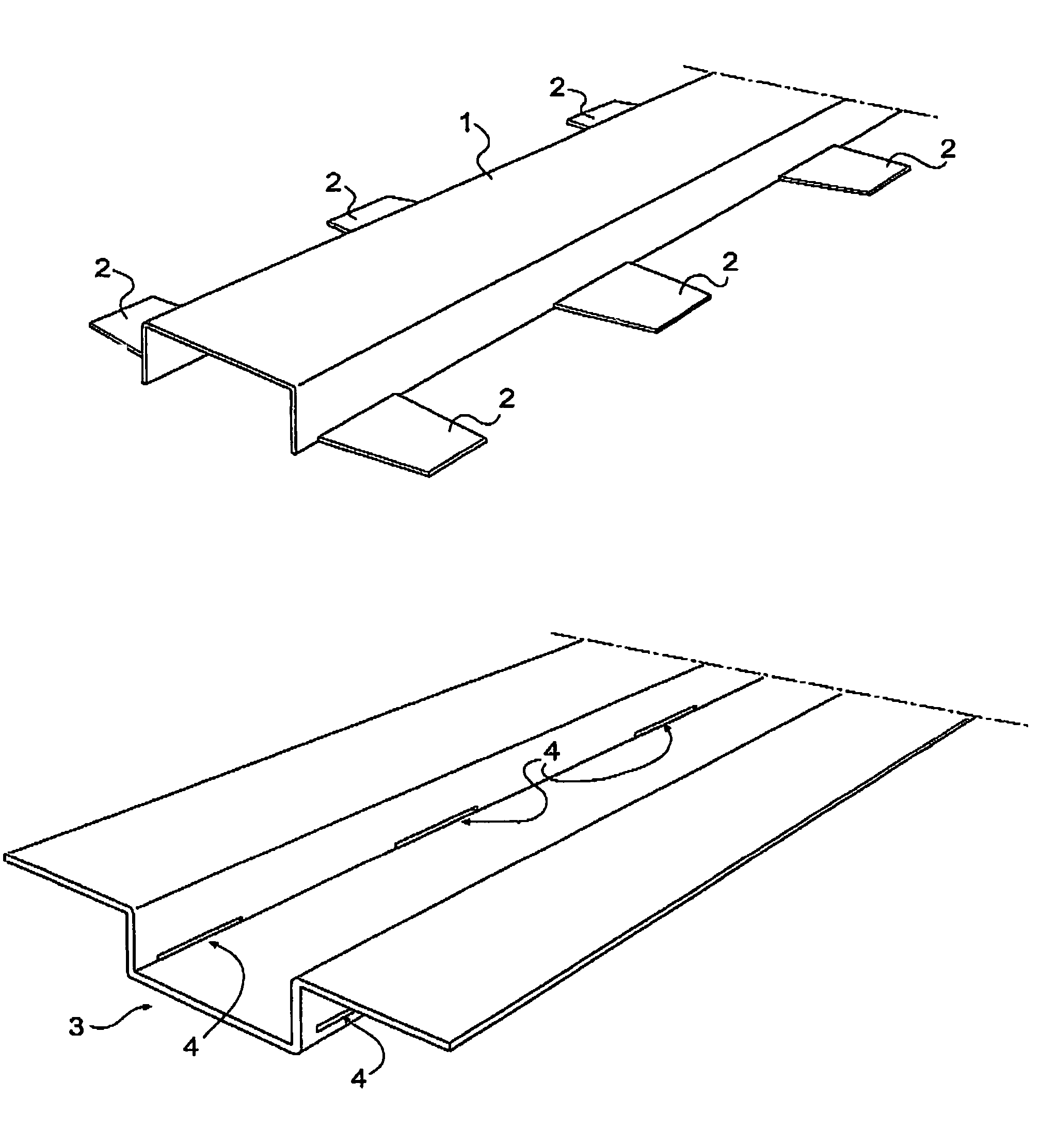
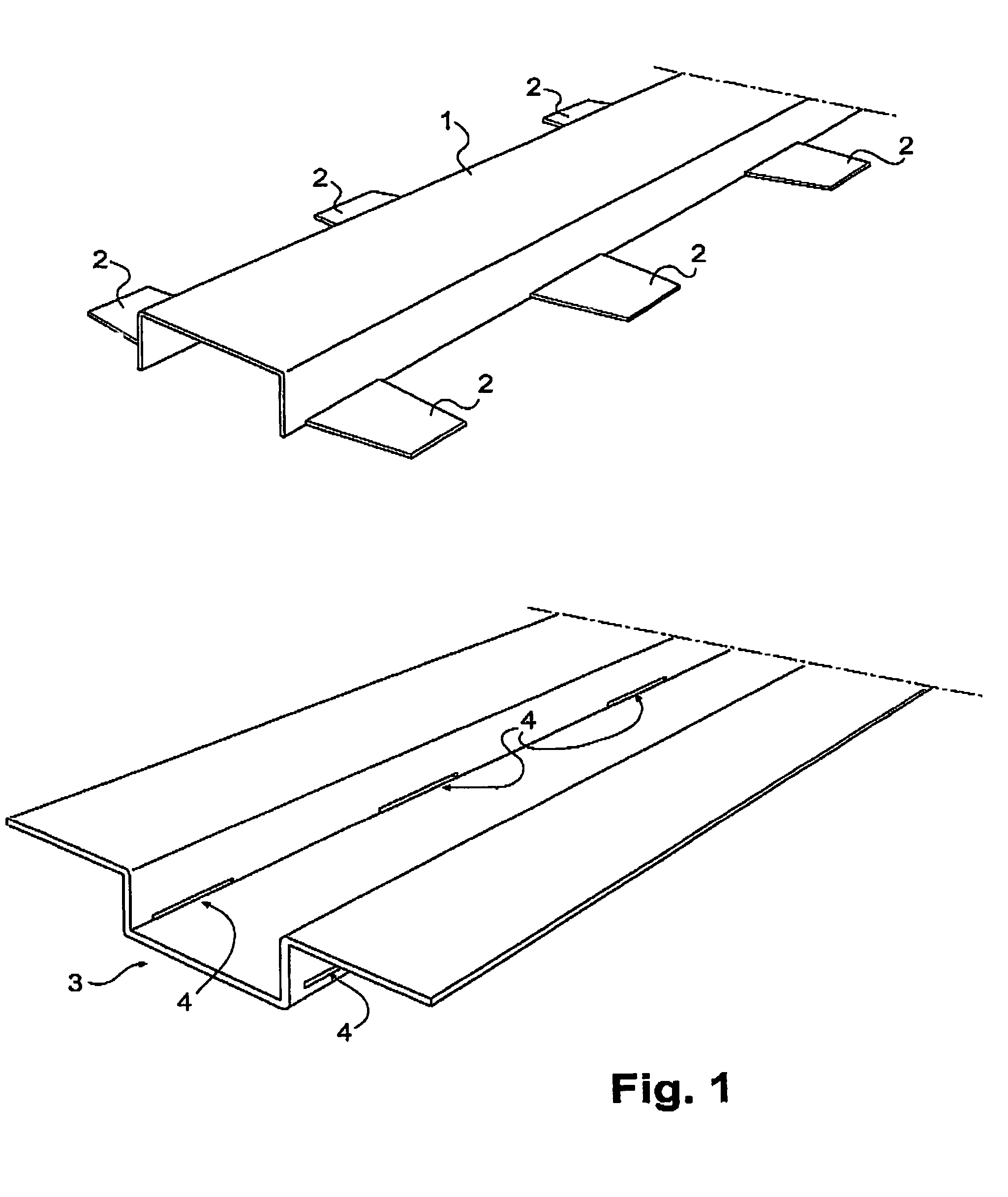
[0015]A contact backing 1 of the desired length is made from stainless sheet steel. Projections 2 are provided on both sides of the contact backing. The finished contact backing is bent at angles.

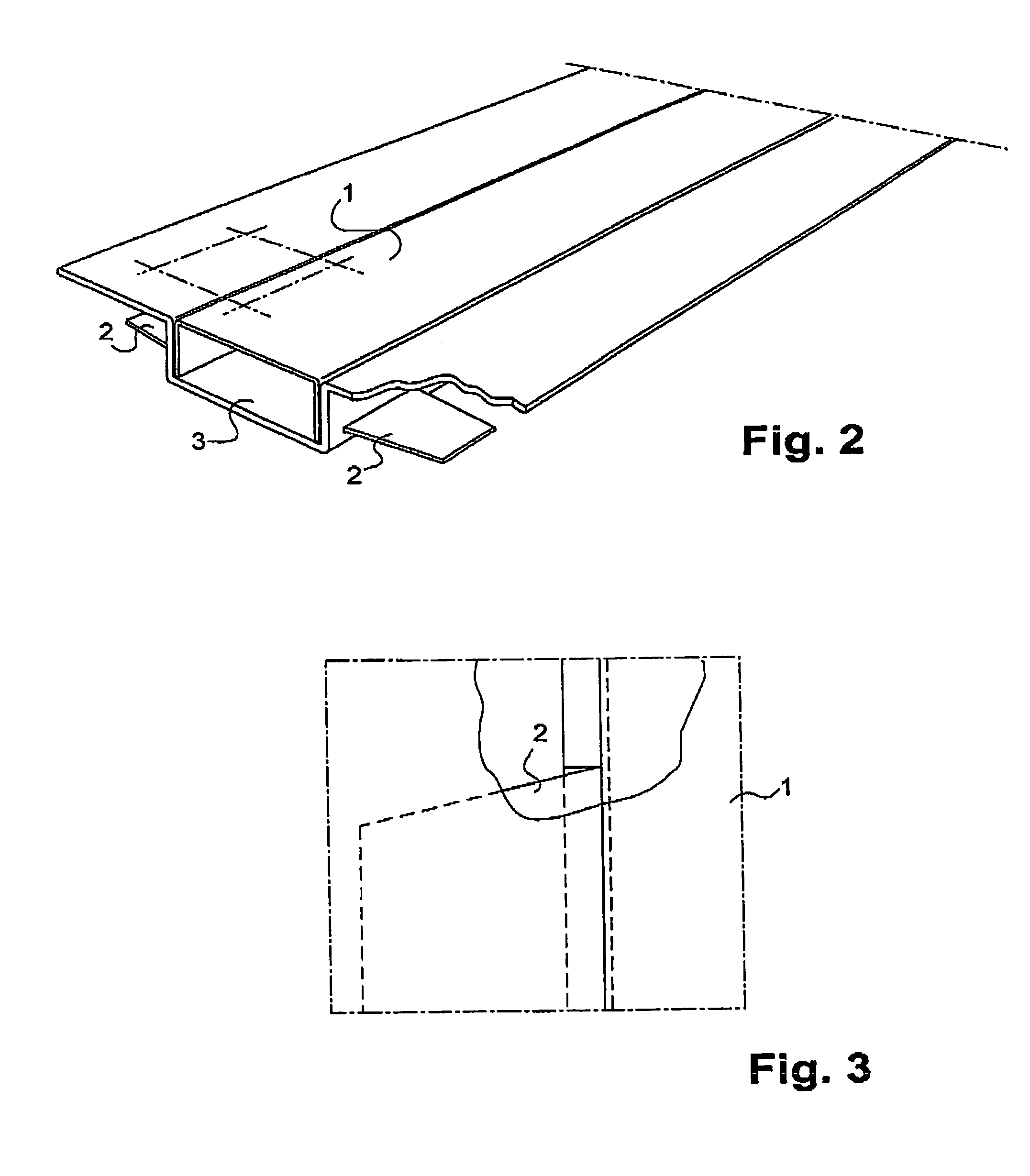
[0016]The contact backing 1 is mounted in advance in a backing groove 3 made of coated steel plate, the other edge of the groove not being bent at this stage. At the bottom of the groove, at both edges, rectangular openings 4 are provided with the same dimensioning as that of the projections 2 on the contact backing. The length of the openings 4 matches the projection 2 of the contact backing with high precision, for the projection to cut material from the precoated sheet steel edge 3 as the members are joined.

[0017]With reference to FIGS. 1-3, the inventive EMI gasket comprises the backing groove (3) with the contact backing (1) mounted in the backing groove. The contact backing has a) an upper horizontal surface, b) first and second vertical sides, c) upper edges of the first and second v...


PUM


Abstract

The invention relates to an EMI gasket formed by joining coated steel (3) and a contact backing (1). The coated steel (3) has elongated openings (4), into which projections (2) provided on the contact backing fit, seizing by their edges the edges of the openings.

Description

BACKGROUND OF THE INVENTION[0001]This invention relates to an EMI gasket formed by joining coated steel and a contact backing.[0002]The EMI gasket of the invention is intended for application to electronic casings and racks to ensure the EMC requirements posed on the finished apparatus. The use of the gasket ensures a completely sealed casing (cf. a Faraday cage) at critical points (of lateral walls).DESCRIPTION OF THE RELATED ART[0003]There are prior art solutions in which an EMI gasket is dimensioned such that contacts directly an electrically conductive surface of precoated sheet steel (cf. an STU casing).[0004]A solution has also been manufactured and tested that comprises an even contact backing made of spring steel for the EMI gasket. This spring steel has made electric contact with the electrically conductive surface of precoated sheet steel. Shield attenuation measurements have indicated attenuation results of only about 30 dB at a frequency of 2,000 MHz.[0005]However, the e...

Claims


Application Information

Patent Timeline
Patent Type & Authority Patents(United States)
IPC IPC(8): H05K9/00H01L23/58
CPCH05K9/0016
Inventor KOHONEN, PETRIIMMONEN, PENTTI
Owner CORIANT
Why Eureka
Try Eureka