Eureka AIR delivers breakthrough ideas for toughest innovation challenges, trusted by R&D personnel around the world.

Electrode cuff with recesses

a technology of electrode contact surfaces and recesses, which is applied in the direction of spinal electrodes, internal electrodes, therapy, etc., can solve the problem that the recesses do not provide a continuous path for current applied by the electrode contact surfaces, and achieve the effect of preventing nerve damag

Active Publication Date: 2013-10-22
MEDTRONIC INC
View PDF229 Cites 58 Cited by
  • Summary
  • Abstract
  • Description
  • Claims
  • Application Information

AI Technical Summary

Benefits of technology

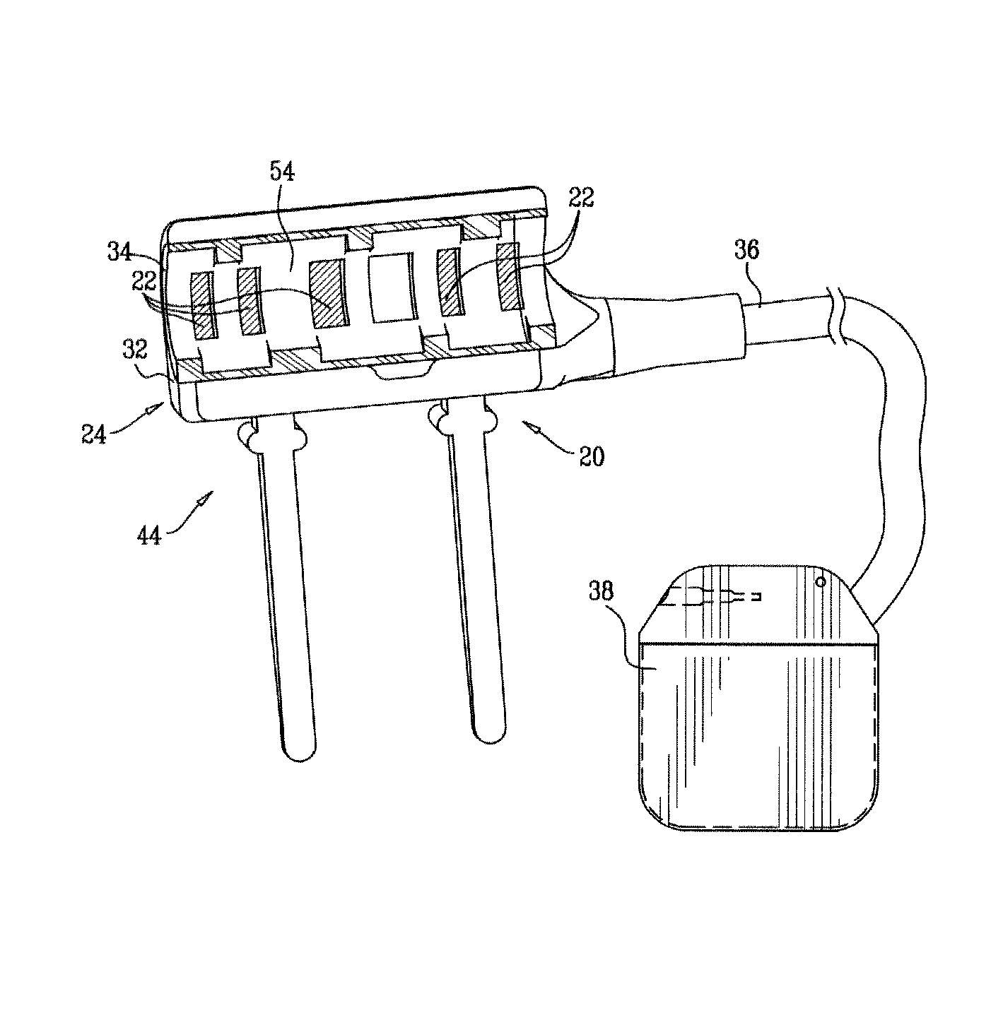
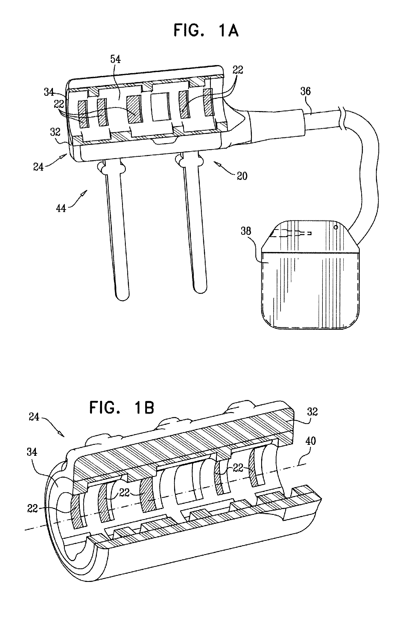
[0003]In some embodiments of the present invention, an electrode assembly for applying current to tubular body tissue, such as a nerve, comprises one or more electrode contact surfaces fixed to a cuff. The cuff is shaped so as to define a plurality of recesses that extend radially outwardly from an innermost surface of the cuff surrounding a longitudinal axis of the cuff. Typically, the cuff is recessed in at least one radially outward direction at every longitudinal location along its entire length. The recesses may serve to prevent damage to the nerve by allowing the nerve to swell in at least one radial direction into at least one of the recesses, along the entire length of the cuff. Providing the recesses generally does not have a material impact on the activation function achieved by the electrode assembly.
[0004]Typically, each of the recesses has a length along the cuff that is less than the entire length of the cuff, e.g., less than 50% or 25% of the length of the cuff. This design generally prevents migration of the nerve over time into the recesses, away from the center of the cuff, as might occur if any of the recesses extended along the entire length, or even most of the length, of the cuff. Holding the cuff in position around the nerve helps maintain good electrical contact between the electrical contact surfaces and the nerve. In addition, because longitudinally adjacent recesses extend in different radially directions, the recesses do not provide a continuous path for current applied by the electrode contact surfaces to pass through the cuff without entering the nerve.
[0005]The cuff is typically shaped such that each perpendicular cross section thereof includes one or more portions that coincide with the innermost surface of the cuff. These non-recessed portions serve in part to hold the cuff in position around the nerve. At the same time, the recesses provide space into which the nerve can swell in varying radial directions along the entire length of the cuff, thereby minimizing any damage the cuff may cause to the nerve. Some of these non-recessed portions further serve in part to electrically isolate longitudinally adjacent recesses from each other along the longitudinal axis of the cuff.

Problems solved by technology

In addition, because longitudinally adjacent recesses extend in different radially directions, the recesses do not provide a continuous path for current applied by the electrode contact surfaces to pass through the cuff without entering the nerve.

Method used


Image

  • Electrode cuff with recesses
  • Electrode cuff with recesses
  • Electrode cuff with recesses

Examples


Embodiment Construction

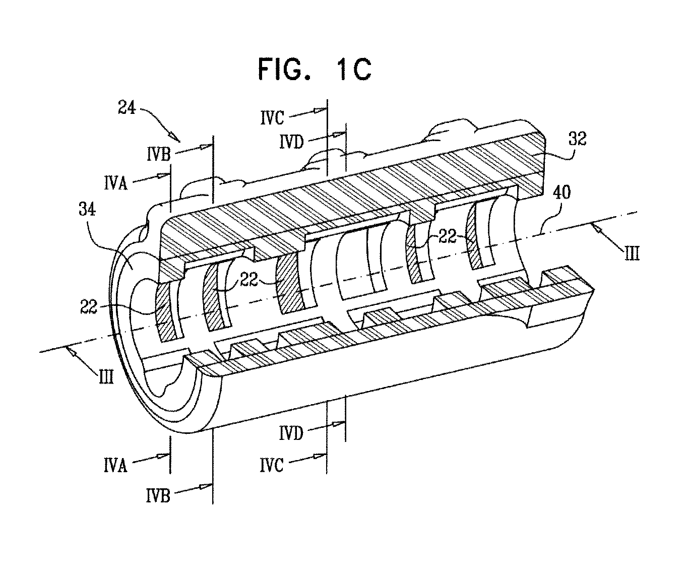
[0194]FIG. 1A is a schematic cut-away illustration of an electrode assembly 20, and FIGS. 1B and 1C are schematic cut-away illustrations of a cuff 24 of electrode assembly 20, in accordance with an embodiment of the present invention. Electrode assembly 20 comprises cuff 24 and one or more electrode contact surfaces 22. Cuff 24 is configured to be placed at least partially around (typically entirely around) a nerve or other tubular body tissue, such as a blood vessel, a muscle, a tendon, a ligament, an esophagus, intestine, a fallopian tube, a neck of a gall bladder, a cystic duct, a hepatic duct, a common hepatic duct, a bile duct, and / or a common bile duct. Cuff 24 defines and at least partially surrounds (typically entirely surrounds) a longitudinal axis 40. The cross section of FIG. 1A shows 180 degrees of a circumference of cuff 24 (i.e., 50% of the cuff; the cuff actually completely surrounds 360 degrees of axis 40), while the cross section of FIG. 1B shows 270 degrees of the ...


PUM


Abstract

An electrode assembly includes one or more electrode contact surfaces, and a cuff, to which the contact surfaces are fixed, and which comprises an electrically insulating material, is configured to assume open and closed positions, and, when in the closed position, is shaped so as to define a plurality of planar cross sections perpendicular to a longitudinal axis of the cuff, distributed continuously along an entire length of the cuff along the longitudinal axis, such that the perpendicular cross sections define respective inner closed curves that together define an inner surface that defines and completely surrounds a volume that extends along the entire length of the cuff. The inner closed curves of at least two of the perpendicular cross sections would cross, and not merely intersect, one another if superimposed while preserving orientation and position of the perpendicular cross sections with respect to the cuff. Other embodiments are also described.

Description

FIELD OF THE APPLICATION[0001]The present invention relates generally to electrical stimulation of tissue, and specifically to methods and devices for regulating the stimulation of nerves or other tissue.BACKGROUND[0002]A number of patents and articles describe methods and devices for stimulating nerves to achieve a desired effect. Often these techniques include a design for an electrode or electrode cuff.SUMMARY OF THE APPLICATION[0003]In some embodiments of the present invention, an electrode assembly for applying current to tubular body tissue, such as a nerve, comprises one or more electrode contact surfaces fixed to a cuff. The cuff is shaped so as to define a plurality of recesses that extend radially outwardly from an innermost surface of the cuff surrounding a longitudinal axis of the cuff. Typically, the cuff is recessed in at least one radially outward direction at every longitudinal location along its entire length. The recesses may serve to prevent damage to the nerve by...

Claims


Application Information

Patent Timeline
Patent Type & Authority Patents(United States)
IPC IPC(8): A61N1/05
CPCA61N1/0556
Inventor BEN-DAVID, TAMIRCOHEN, EHUDGAVISH, NOAMAYAL, SHAI
Owner MEDTRONIC INC
Why Eureka
Eureka Blog
Learn More