Membrane based electrochemical cell stacks

Active Publication Date: 2005-11-03
SILICON VALLEY BANK
View PDF6 Cites 63 Cited by
  • Summary
  • Abstract
  • Description
  • Claims
  • Application Information

AI Technical Summary

Benefits of technology

[0037] This novel design feature eliminates the need for costly external fittings and enhances ease of assembly for the end user. Several other benefits are associated with the use of the integrated tube fittings. For example, tubing can be readily “cut to order” by the end user. Additionally, since there is no compression seal in the final assembly, per se, between the fitting and endplates, the opportunity for leakage is reduced or eliminated at that site. Still other advantages provided by this embodiment include an increased internal diameter, elimination of a flow restriction in that it allows significantly more flow per manifold area, resulting in a smaller overall product.
[0038] In yet another preferred embodiment of the invention, fuel cell stacks of the invention comprise encapsulated current collectors. The encapsulated current collectors offer several benefits relative to the conventional current collectors which may be exposed to the environment and internal fluids.
[0039] The current collectors in this embodiment are positioned internally on either side of the endplates of the stack; only their respective wire connections protrude from the stack assembly. In that way, the encapsulated current collector is not exposed to the environment or to internal fluids. It also is relatively inexpensive in that susceptibl

Problems solved by technology

However, the high cost of fuel cells when compared to conventional power generation technology deters their widespread use.
The cost of fabricating and assembling fuel cells can be significant, due to the materials and labor involved.
These processes are labor intensive and not conducive to high volume manufacturing, thereby adding to the high cost of fuel cells.
Additionally, the variability of these processes results in poor manufacturing yield and poor device reliability.
Fuel cell stacks range in design depending upon-power output, cooling, and other technical requirements, but may utilize a multitude of MEAs, seals, flow fields and separator plates, in intricate assemblies that result in manufacturing difficulties and further increased fuel cell costs.
These conventional means of applying compression add even more components and complexity to the stack and pose additional sealing requirements.
Other disadvantages observed in connection with some conventional fuel cell stacks are electrical in nature.
For example, depending upon the configuration of the fuel cell and the degree of exposure of the MEA to the reactants and waste streams in the various manifolds providing reagents and coolants to the flow fields, a cross-cell potential problem may a

Method used


Image

  • Membrane based electrochemical cell stacks
  • Membrane based electrochemical cell stacks
  • Membrane based electrochemical cell stacks

Examples


example 1

Vacuum Assisted Resin Transfer Molding

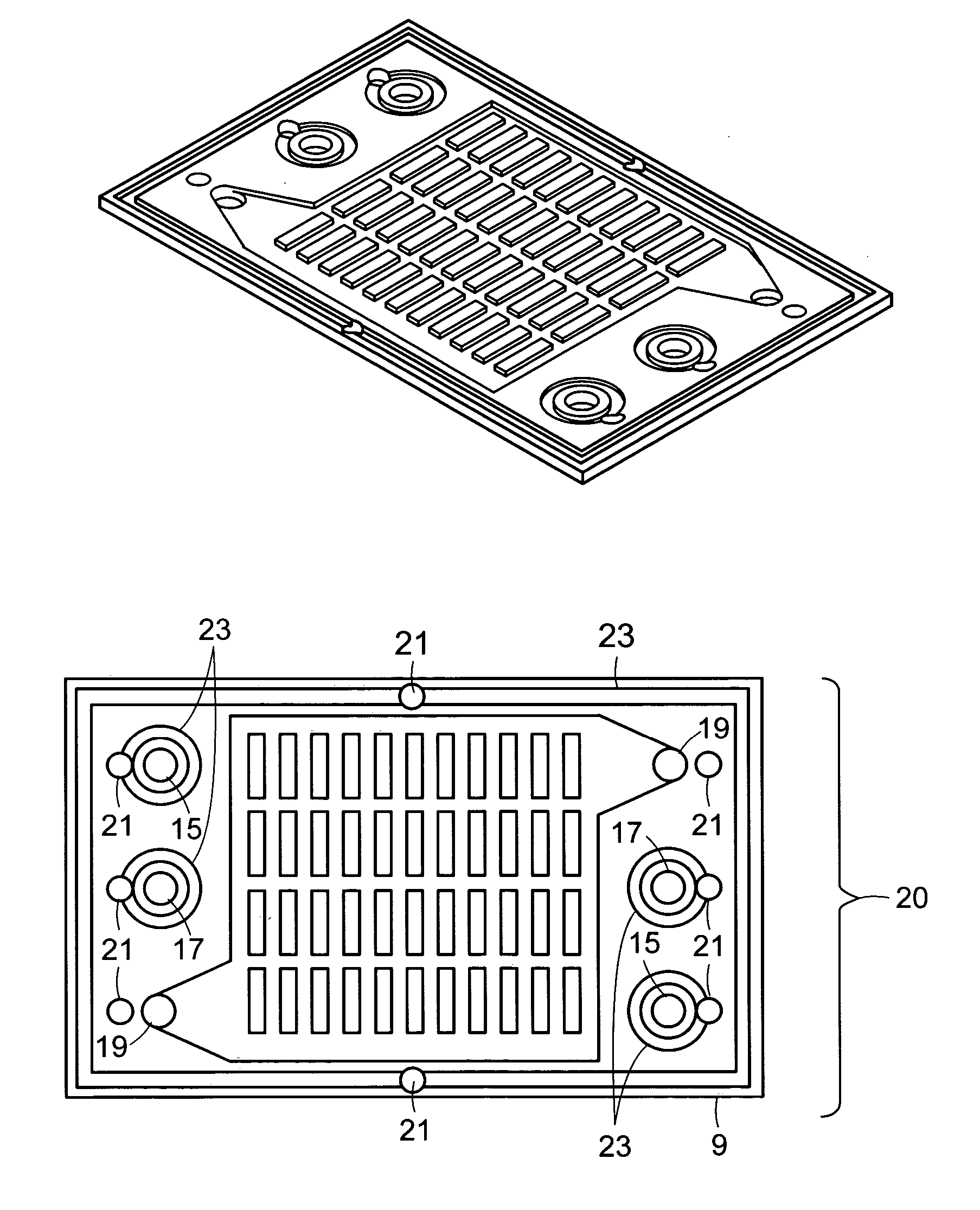
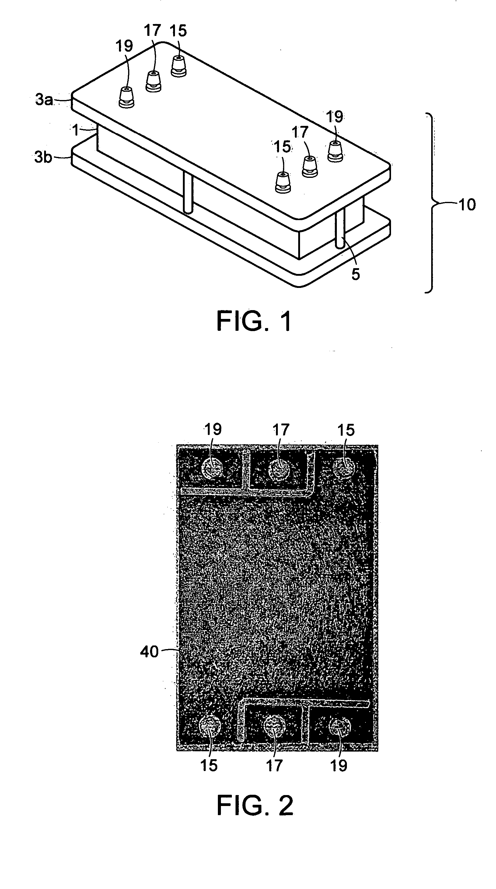
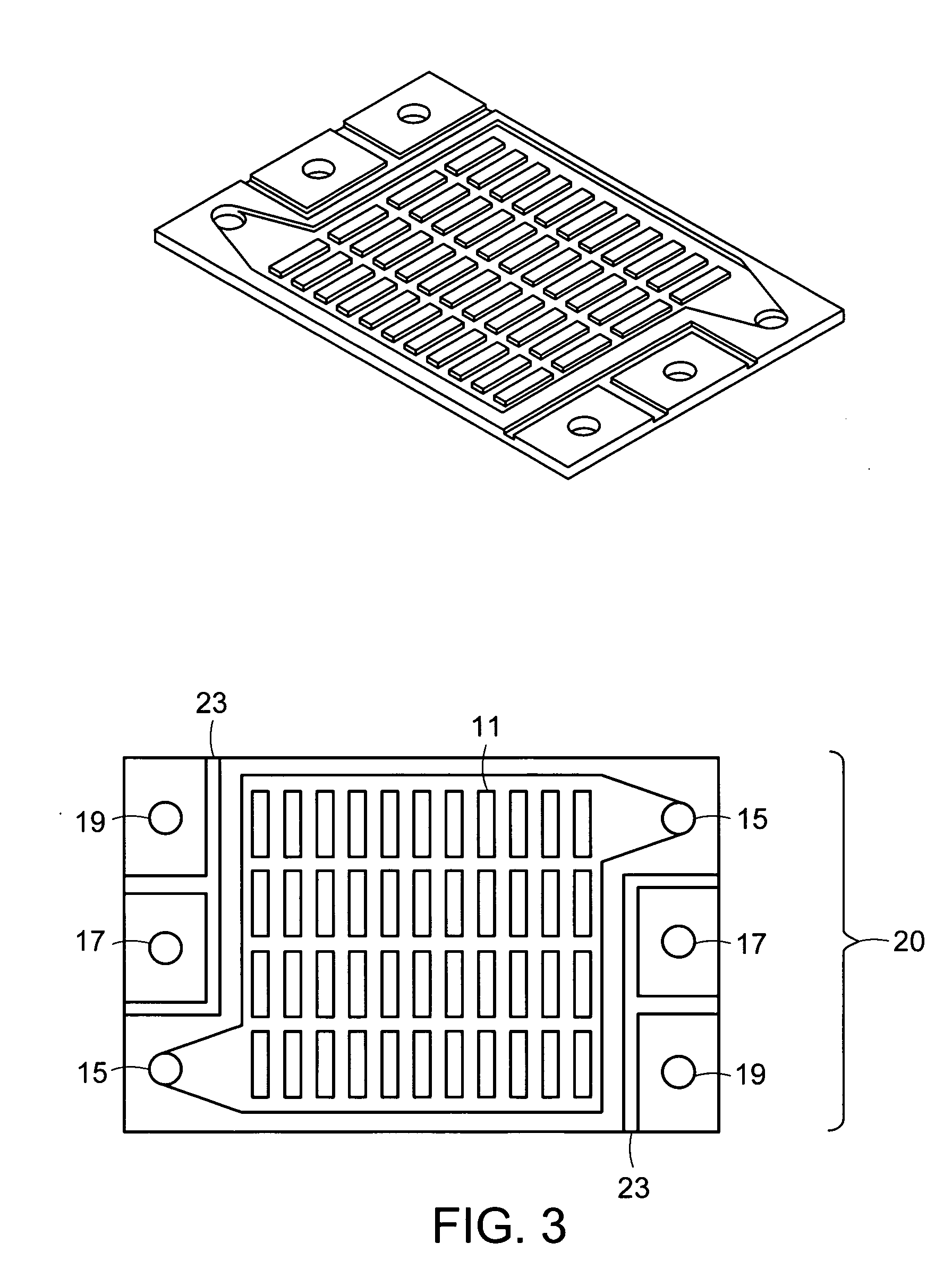
[0114] Using the groove and sealant hole pattern depicted in FIG. 3, bipolar plates were machined in polymer graphite composite (with the oxidant flow field shown on one side and the fuel flow field on the other). MEAs were made using known processes and cut according to the pattern shown in FIG. 7, e.g., cut nominally to the same outside dimensions as the bipolar plates with the same pattern of manifold holes. Six MEAs, five bipolar plates, and two terminal plates were assembled in the mold shown in FIG. 8 in the following order: terminal plate, MEA, bipolar plate, MEA, bipolar plate, MEA, bipolar plate, MEA, bipolar plate, MEA, bipolar plate, MEA, terminal plate. The assembly was encapsulated with the silicone resin, Silastic M, (available commercially from The Dow Corning Corporation of Midland, Mich., USA) by applying a vacuum of 23 inches Hg for approximately 90 seconds. (See also FIG. 15 for a plot of the current and voltage curve of the...

example 2

Pressure Assisted Resin Transfer Molding

[0115] A fuel cell stack was fabricated from endplates, composite MEAs and bipolar plates via encapsulation in silicone. Endplates were machined from aluminum with treaded holes corresponding to manifolds for hydrogen in and out, air in and out, and cooling in and out, as well as holes for the addition of sealant. These endplates were coated with gold to improve their contact resistance and corrosion stability, thereby functioning as endplates and current collectors. MEAs were cut from a larger 5 layer piece (membrane with catalyst and gas diffusion layer on each side) and a silicone gasket was bonded to the periphery (see FIG. 13 for example). Holes were punched in the gasket portion of the MEAs corresponding to the manifolds ports and sealant holes. Bipolar plates were machined from graphite polymer composite with two varieties; with a fuel and an oxidant flow fields [A-A′] and with a fuel flow field and a coolant flow field [A-B] or an ox...

example 3

Pressure Assisted Resin Transfer Molding II

[0119] A fuel cell stack was fabricated from endplates, composite MEAs and bipolar plates via encapsulation in silicone. Endplates were machined from ABS plastic with holes corresponding to manifolds for hydrogen in and out, air in and out, and cooling in and out, as well as holes for the addition of sealant (see figures pages 19, 21 for example). Silicone tubes were fashioned with a lip to fit within the endplate holes corresponding to the various flows (see figure page 22 for example). Current collectors fabricated from flat sheet copper coated with gold to improve their contact resistance (see figure page 20 for example). Wires were soldered to the current collectors. MEAs were cut from a larger 5 layer piece (membrane with catalyst and gas diffusion layer on each side) and a silicone gasket was bonded to the periphery (see FIG. 13 for example). Holes were punched in the gasket portion of the MEAs corresponding to the manifold ports an...


PUM

PropertyMeasurementUnit
Partial pressureaaaaaaaaaa
Pressureaaaaaaaaaa

Abstract

The present invention provides membrane cassettes and stacks thereof which are suitable for a use in a variety of electrochemical applications. The invention further provides membrane cassettes which comprise one or more bipolar plates which have one or two reactant or coolant flow fields consisting of at least one groove in opposing surfaces of the bipolar plate. In certain preferred embodiments, the invention provides cassettes and stacks which are suitable for use in fuel cell applications. Particularly preferred embodiments of the invention include design improvements which enhance the performance and reliability of certain components of the fuel cell stack.

Description

[0001] This application is a continuation-in-part of International Application PCT / US03 / 12684, filed on Apr. 23, 2003, which in turn claimed the prior benefit of U.S. Provisional Patent Application 60 / 374,631, filed on Apr. 23, 2002.FIELD OF INVENTION [0002] This invention relates to membrane-based electrochemical cells, and more particularly, to proton exchange membrane (PEM) fuel cell stacks. The present invention also describes novel processes for producing these PEM fuel cell stacks. BACKGROUND OF THE INVENTION [0003] Membrane based electrochemical cells, and particularly, proton exchange membrane (PEM) fuel cells are well known. PEM fuel cells convert chemical energy to electrical power with virtually no environmentally harmful emissions and differ from a battery in that energy is not stored, but derived from supplied fuel. Therefore, a fuel cell is not tied to a charge / discharge cycle and can maintain a specific power output as long as fuel is continuously supplied. The large ...

Claims


Application Information

Patent Timeline
IPC IPC(8): H01M2/08H01M8/02H01M8/04H01M8/10H01M8/24
CPCH01M8/0206Y02E60/50H01M8/0247H01M8/0258H01M8/0267H01M8/0273H01M8/0276H01M8/0284H01M8/0286H01M8/0297H01M8/04007H01M8/04074H01M8/04089H01M8/04201H01M8/242H01M8/2475H01M8/248H01M2008/1095H01M8/0228H01M8/241H01M8/2483
Inventor OSENAR, PAULSABIN, PAULENAYETULLAH, MOHAMMADFORMATO, RICHARD M.
Owner SILICON VALLEY BANK
Why Eureka
Try Eureka