
Shakeproof and dampproof dynamic battery unit

A technology for power battery packs and battery cells, applied to battery pack components, secondary batteries, circuits, etc., can solve problems such as poor battery working stability, damaged batteries, short circuits, etc., to achieve reliability and stability, and good shock resistance Performance, the effect of extending the working life

Inactive Publication Date: 2008-08-06
GUANGZHOU ZHANHUI ELECTRONICS
View PDF0 Cites 46 Cited by
  • Summary
  • Abstract
  • Description
  • Claims
  • Application Information

AI Technical Summary

Problems solved by technology

Some of the batteries are directly placed in the battery box. This installation method lacks the necessary fixing of the batteries, making the electrical contact of the batteries unreliable. External vibrations can easily affect the state of the batteries. The working stability is very poor in a vibrating environment; some cells are tightly fixed together. Although this method solves the problem of shock resistance of the battery to a certain extent, but the multiple cells are squeezed together, which is not conducive to battery life. The heat dissipation when the core is working also affects the working stability of the battery
In addition, most of the casings of existing power batteries are composed of a top casing and a bottom casing. The connection between the two is either a snap-fit ​​structure, or the two are fixed by screws. The waterproof effects of the above two connection methods of the casing are both Relatively poor, when used in a humid or rainy environment, the circuit board inside the battery can easily fail to work or short circuit due to moisture, and even damage the battery

Method used


Image

  • Shakeproof and dampproof dynamic battery unit
  • Shakeproof and dampproof dynamic battery unit
  • Shakeproof and dampproof dynamic battery unit

Examples


Embodiment Construction

[0022] Below in conjunction with the best embodiment shown in the accompanying drawings, it will be further described in detail.

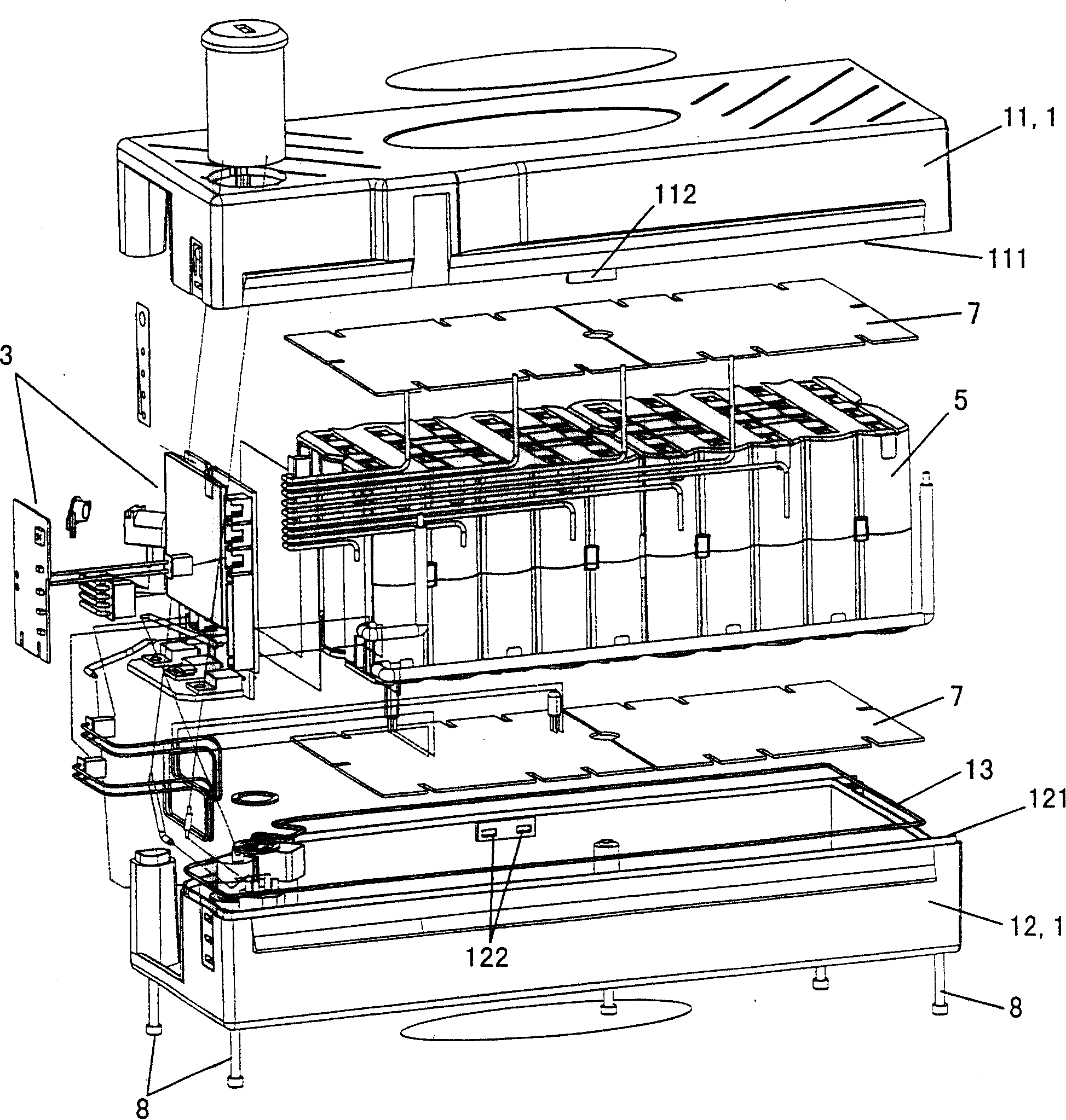
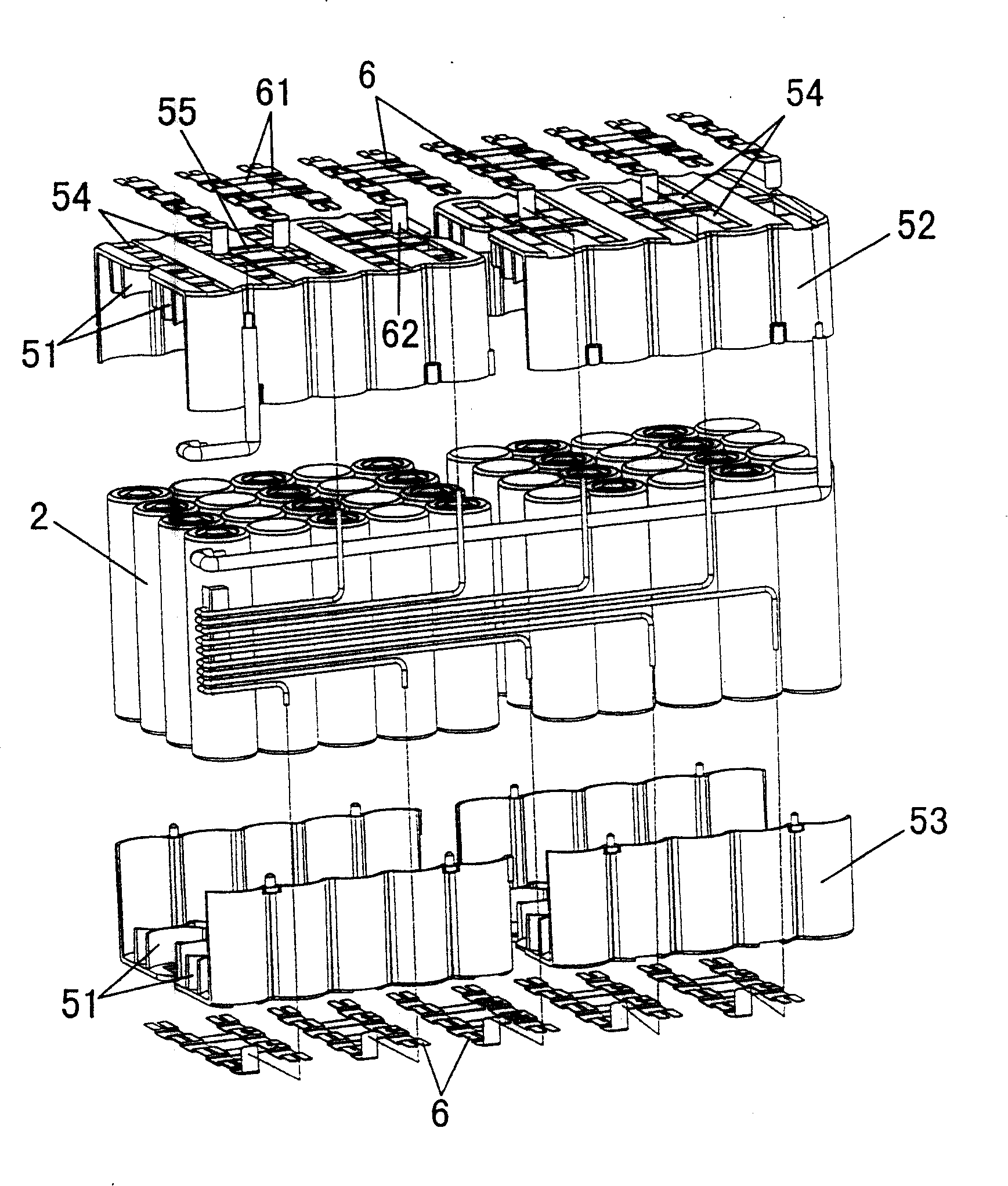
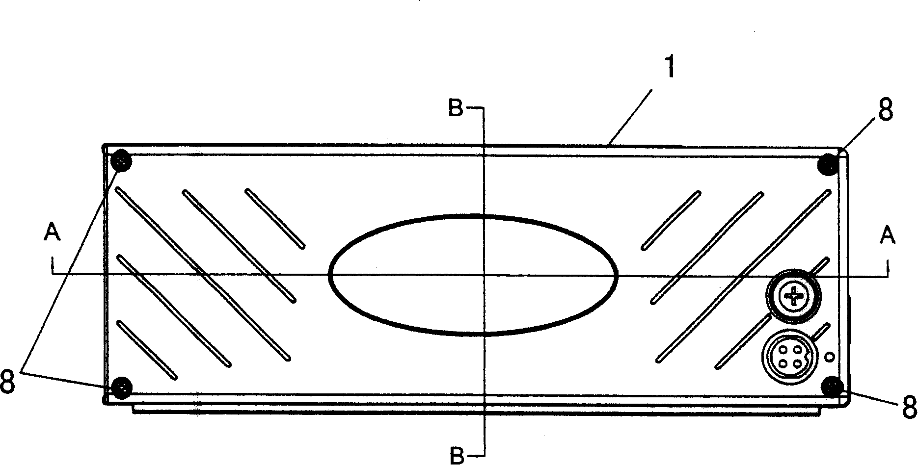
[0023] Such as figure 1 and figure 2 As shown, the anti-shock and moisture-proof power battery pack of the present invention includes a casing 1, a plurality of cells 2 arranged in the casing 1, a charge-discharge and charge-discharge protection circuit board 3 electrically connected to the cells 2, and a circuit board for placing And fix the support structure 5 of the plurality of electric cores 2 . The support structure 5 fixes each battery cell 2 in the axial and radial directions, and maintains a certain distance between each battery cell 2 to facilitate heat dissipation when the battery cell 2 is working.

[0024] Such as figure 2 As shown, the bracket structure 5 is joined by an upper cover 52 and a lower cover 53 to form a box structure. The upper cover 52 has front and rear side walls and a top surface, and a plurality of radial posit...


PUM


Abstract

The invention relates to a shock-resistant and damp-proof power battery set which comprises an outer shell (1), a plurality of cells (2) arranged inside the outer shell (1) and a charging / discharging protection circuit board (3) in electric connection with the plurality of cells (2), wherein a support structure (5) constraining the positions of the plurality of cells (2) axially and radically is fixed in the outer shell (1), the plurality of cells (2) constrained in the support structure (5) are arranged with a clearance in between. The cells in the battery set can be positioned reliably to keep a sound electric contact, has very good shock-resistant performance and heat dispersion performance and is very suitable to be used on various power battery sets in shaking circumstances.

Description

technical field [0001] The invention relates to a rechargeable power supply device, in particular to a lithium ion battery pack for providing vehicle power supply. Background technique [0002] Existing rechargeable power sources, such as power batteries used in electric bicycles, generally use multiple cells connected in parallel or in series to expand the capacity of the battery and increase the voltage of the battery. Some of the batteries are directly placed in the battery box. This installation method lacks the necessary fixing of the batteries, making the electrical contact of the batteries unreliable. External vibrations can easily affect the state of the batteries. The working stability is very poor in a vibrating environment; some cells are tightly fixed together. Although this method solves the problem of shock resistance of the battery to a certain extent, but the multiple cells are squeezed together, which is not conducive to battery life. The heat dissipation w...

Claims


Application Information

Patent Timeline
IPC IPC(8): H01M2/10H01M2/34H01M2/20H01M10/00H01M50/24H01M50/242H01M50/244H01M50/249H01M50/502H01M50/584
CPCY02E60/10
Inventor 李智董超祺
Owner GUANGZHOU ZHANHUI ELECTRONICS
Learn More