

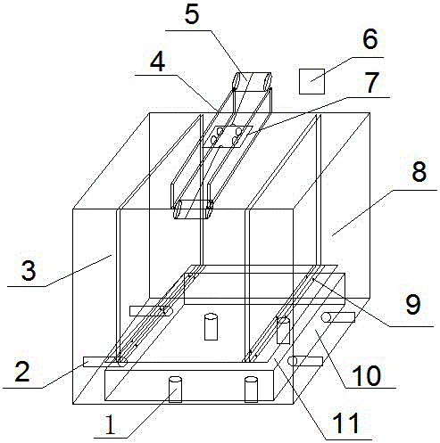
Dynamic cyclic load retaining wall model test device and test method
A model test device and retaining wall technology, which is applied in the fields of geotechnical engineering, road engineering, and railway engineering, to achieve the effects of easy molding, good durability, and easy local materials
- Summary
- Abstract
- Description
- Claims
- Application Information
AI Technical Summary
Problems solved by technology
Method used
Image

Examples
Embodiment 1
[0058] (1) Model installation: sand is used as filler, and the degree of compaction is controlled at 85%;
[0059] (2) Read the initial pressure of the lateral earth pressure cell of the rotating retaining wall and the initial displacement of the dial gauge;
[0060] (3) Control the vertical jack through the controller 6, so that the pressurization time is 3s, the decompression time is 3s, pressurization and decompression are repeated, and stop after five minutes of decompression. Taking the five-minute stop time as the starting point, measure the earth pressure and displacement every minute, and analyze the earth pressure and displacement changes of the retaining wall in different periods after the end of the vertical seismic wave;
[0061] (4) In step (3), if the seismic loading platform is broken, the loading platform needs to be replaced again.
Embodiment 2
[0063] (1) Model installation: silt is used as filler, and the degree of compaction is controlled at 90%;
[0064] (2) Read the initial pressure of the lateral earth pressure cell of the rotating retaining wall and the initial displacement of the dial indicator;
[0065] (3) Keep the pressure of the vertical jack constant, and control the horizontal jack through the controller 6. While the left side is pressurized for 3 seconds, the right side is decompressed for 3 seconds, then the left side is decompressed for 3 seconds, the right side is pressurized for 3 seconds, and the pressure is reciprocated. Pressure, stop after five minutes of increasing and decreasing pressure. Taking the five-minute stop time as the starting point, measure the earth pressure and displacement every minute, and analyze the earth pressure and displacement changes of the retaining wall in different periods after the end of the ground level seismic wave;
[0066] (4) In step (3), if the seismic loading...
Embodiment 3
[0068] (1) Model installation: sand is used as filler, and the compaction degree is controlled to 90%;
[0069] (2) Read the initial pressure of the lateral earth pressure cell of the rotating retaining wall and the initial displacement of the dial indicator;
[0070] (3) Keep the pressure of the vertical jack and the horizontal jack constant. The initial position of the loading vehicle is at one end of the model slot. The loading vehicle is covered with steel blocks so that the converted axle load of the vehicle is 100KN. The speed of the traction motor is controlled by the controller 6 so that The loading cart produces a running speed of 40Km / h. And according to the length of the slide rail, the running time of the motor is determined to be 0.18s. During the operation of the front-end traction motor for 0.18s, the rear-end traction motor does not work, and then the rear-end traction motor works for 0.18s, and the front-end traction motor does not work. Repeatedly run 1000 ti...
PUM
 Abstract
Description
Claims
Application Information