
Storm shutter retention bar

a technology of shutters and bars, applied in shutters/movable grilles, building locks, constructions, etc., can solve the problems of many windows including windows within doors that can fail, windows and glass laden doors weakest points of any building, etc., and achieve the effect of simple design and construction, quick and easy us

Inactive Publication Date: 2009-08-06
STINSON CHRISTOPHER L
View PDF26 Cites 5 Cited by
  • Summary
  • Abstract
  • Description
  • Claims
  • Application Information

AI Technical Summary

Benefits of technology

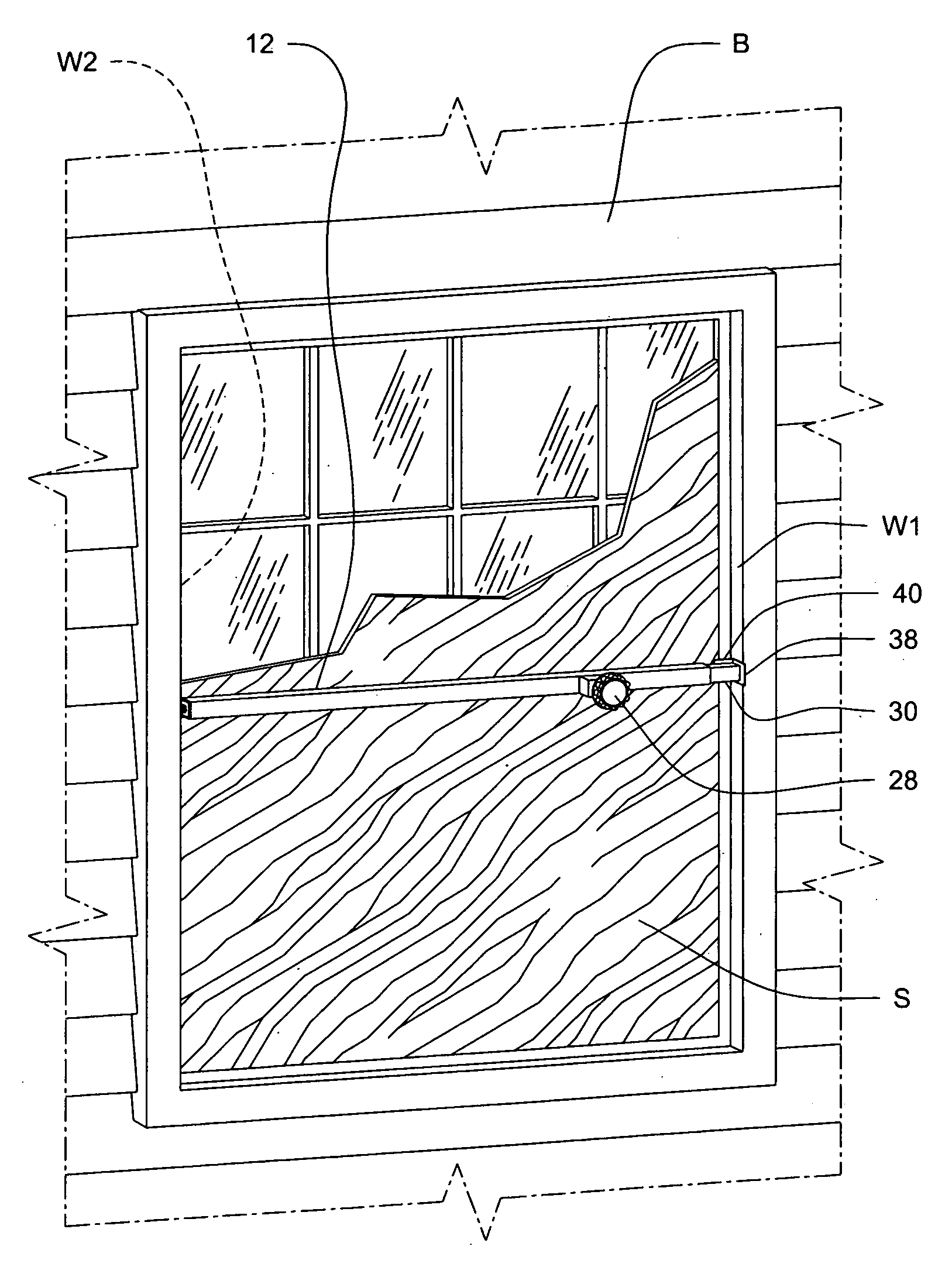
[0009]The storm shutter attachment bar of the present invention addresses the aforementioned needs in the art. The storm shutter retention bar secures a plywood shutter within a window opening of a building in order to allow the plywood shutter to protect the window against wind forces and flying debris. The storm shutter retention bar does not penetrate into or otherwise damage the building upon which the bar is being used. The storm shutter retention bar is of relatively simple design and construction and is relatively quick and easy to use so that a building owner can install several storm shutter retention bars about a building in short order in order to give the owner an opportunity to evacuate the impending storm area.
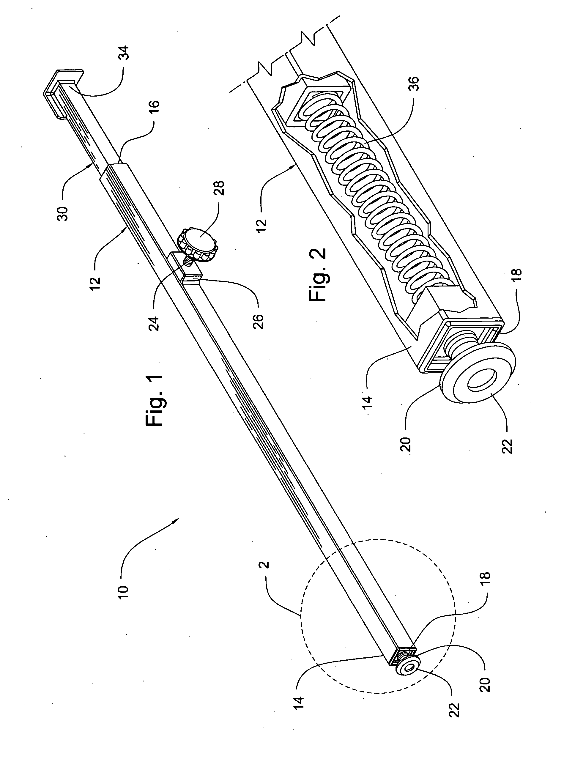
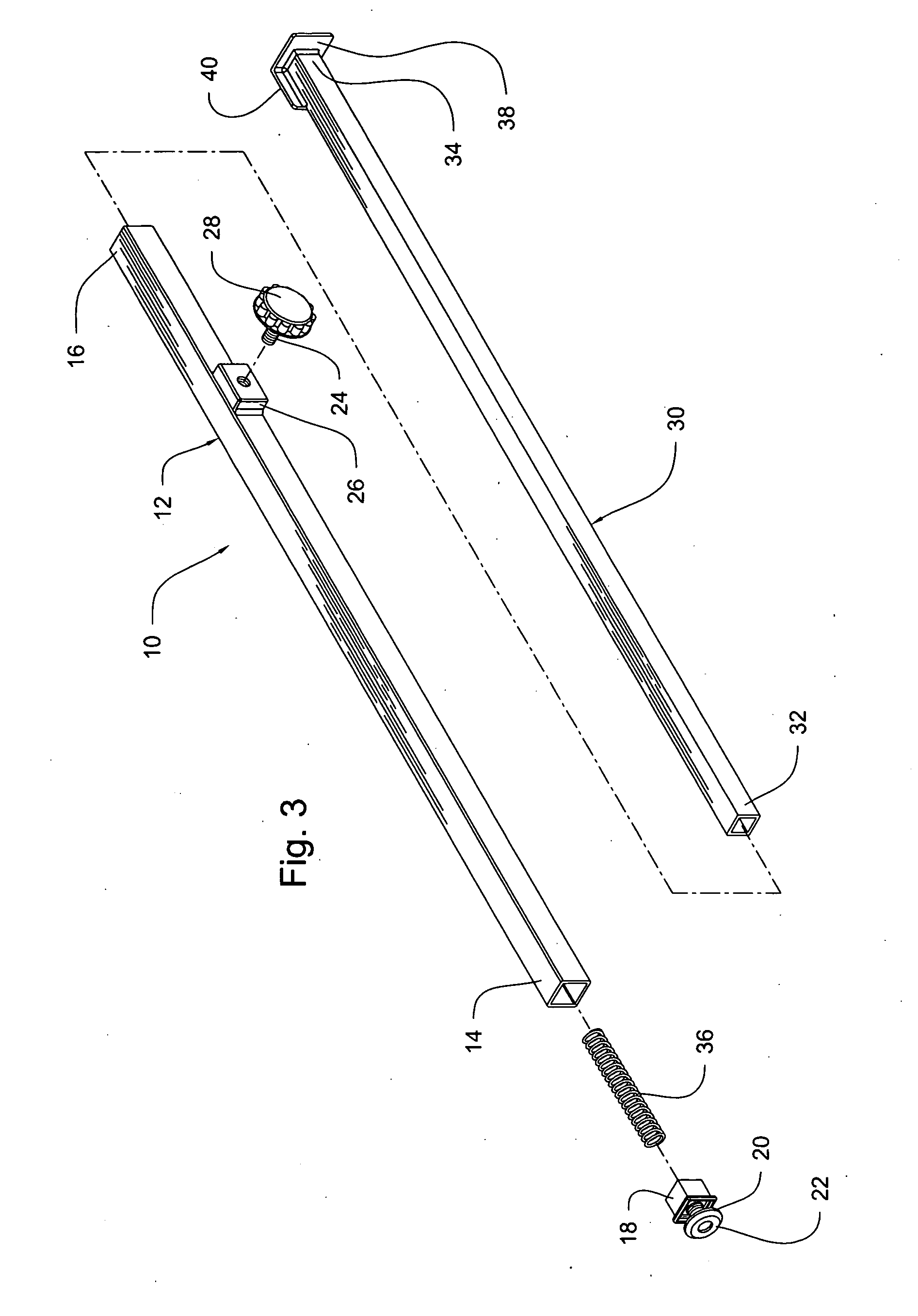
[0010]The storm shutter retention bar of the present invention is comprised of a retention bar that has a first hollow tubular member with a closed first end and an open second end and a second tubular member that has a third end and a fourth end such that the third end is received within the first tubular member so that the second tubular member is partially and slidably received within the first tubular member. A locking mechanism is attached to the first tubular member for selectively preventing sliding of the second tubular member within the first tubular member. A foot is threadably attached to the first end of the first tubular member. A spring is disposed within the first tubular member and has a fifth end that abuts the first end of the first tubular member and a sixth end that abuts the third end of the second tubular member. The retention bar is positioned between a first surface and an opposing second surface of a building such that the first end of the first tubular member abuts against the first surface and the fourth end of the second tubular member abuts against the second surface and such that the spring acts on and loads the first tubular member and the second tubular member and the locking mechanism prevents movement of the second tubular member with respect to the first tubular member and such that the foot is rotated in order to give the retention bar a desired overall length. The foot is capable of pivoting. The locking mechanism comprises a shaft that threadably passes through the first tubular member and frictionally acts on the second tubular member in order to prevent movement of the second tubular member with respect to the first tubular member. A handle is attached to the shaft for rotating the shaft. A first plate member is attached to the fourth end of the second tubular member such that the first plate abuts the second surface of the building. The first plate is positioned in transverse orientation with a longitudinal axis of the second tubular member. A second plate is attached to an outer surface of the second tubular member and is positioned in parallel orientation with a longitudinal axis of the second tubular member and the second plate abuts the shutter. The foot has a first diameter and the first hollow tubular member has a second diameter that is at least as large as the first diameter of the foot. A wrench is used to rotate the foot when the device is deployed in holding a shutter within a building opening. The second hollow tubular member is substantially received within the first hollow tubular member which means that the second tubular member passes at least half way down into the hollow interior of the first tubular member when the device is deployed.

Problems solved by technology

One of the weakest points of any building, whether the building has been built to tough modern standards or was built several years prior, are the windows and glass laden doors.
Many windows including windows within doors can be fail due to the pressure loading exerted on the pane when a strong wind acts on the building.
Even if the window is of solid construction, unless the pane if made from impact resistant glass, which is extremely expensive to manufacture and install, the window is subject to failure if an object strikes the pane with sufficient force.
Such ingressing winds begin to act on the roof of the building and if the winds are of sufficient strength, the roof can be lifted off from the remainder of the building, resulting in catastrophic failure of the building.
While plywood shutters work reasonably well, and have protected countless structures from the wind forces of a tropical system, use of the plywood shutters requires a destructive intrusion into the building.
While a series of holes is much better than coming back to a pile of rubble where the building once stood, such holes are unsightly and require repairs.

Method used


Image

  • Storm shutter retention bar
  • Storm shutter retention bar
  • Storm shutter retention bar

Examples


Embodiment Construction

[0016]Referring now to the drawings, it is seen that the storm shutter retention bar of the present invention, generally denoted by reference numeral 10, is comprised of a first hollow tubular member 12 that has a closed first end 14 and an open second end 16. The closed first end 14 of the first tubular member 12 may be either monolithic and / or integral with the remainder of the first tubular member 12, or as seen, an end cap 18 may be attached, removably or otherwise, to the first tubular member 12 in order to create the closed first end 14. A foot 20 is threadably attached to the end cap 18 (or directly to the first end 14 of the first tubular member 12 in the case of monolithic and / or integral construction). The foot 20 is capable of pivoting and may have a non-slip tip 22 on its end. The diameter of the foot 20 is no greater than the outer diameter of the first tubular member 12. A shaft 24 threadably passes through the first tubular member 12. As the walls of the first tubular...


PUM


Abstract

A retention bar holds a shutter in place against a window within a window opening of a building, the retention bar having a first tubular member and a second tubular member that slides within the first member. The retention bar is positioned against a pair of opposing surfaces of the window opening, windward of the shutter, and the two tubular members are locked to one another. A spring loads the two tubular members against the window surfaces. A foot is threadably attached to an end of the first tubular member and provides fine length adjustment of the retention bar. A pair of plates is located on an end of the second tubular member, which plates lay against the window opening surface and the shutter respectively.

Description

BACKGROUND OF THE INVENTION[0001]1. Field of the Invention[0002]The present invention relates to a retention bar that holds a storm shutter in place against a window within a window opening on a building without the need to penetrate into the building.[0003]2. Background of the Prior Art[0004]In recent years, the hurricane seasons have become more active, producing a higher than average number of storms and at higher categories, on average, on the Stafford-Simpson scale. These tropical system storms, which can cover vast areas, can come ashore and pack a punch onto affected residents especially those living along coastal areas. Fortunately, modern technology allows most tropical systems to be tracked for several days before landfall and also allow, within a reasonable degree of certainty, the predicated area of landfall. As such, people in the affected areas can make preparations to get out of harm's way. Such preparations include securing homes and other buildings and getting to a ...

Claims


Application Information

Patent Timeline
IPC IPC(8): E05B65/00E06B5/10
CPCE05C19/003E06B2009/005E06B9/02Y10T70/5093
Inventor STINSON, CHRISTOPHER L.
Owner STINSON CHRISTOPHER L
Learn More