Taping Apparatus

a tape applicator and tape cutting technology, applied in the field of painting, can solve the problems of difficult to accurately and quickly tap the edge, difficult to apply the process, and difficult to quickly and accurately cut the edge, etc., to achieve the effect of simple one-handed operation, quick and accurate tape application, and simple tape application

Inactive Publication Date: 2009-11-05
PYLES CHRISTOPHER PYLES
View PDF25 Cites 5 Cited by
  • Summary
  • Abstract
  • Description
  • Claims
  • Application Information

AI Technical Summary

Benefits of technology

[0006]A primary object and / or advantage of the present invention is to combine the speed and precision of a tape applicator with a tape cutting mechanism that accurately measures and cuts the tape to fit into inside corners. This tape cutting mechanism allows a user to take advantage of the efficiency of a tape applicator to apply tape quickly and accurately up to the edge of a surface and the ability to cut the tape off to the correct length without requiring the use of additional measuring or cutting tools.
[0007]A more specific object and / or advantage of the present invention is to provide a taping applicator cutting mechanism that will cut the tape to a desired length and substantially orthogonal to fit into an inside corner.
[0008]Another object and / or advantage of the present invention is to make the applying and cutting of the tape simple enough for one-handed operation.
[0009]A further object and / or advantage of the present invention is to make the cutting mechanism safe to use and handle.
[0010]Still further object and / or advantage of the present invention is to provide a device that will cleanly cut the tape without leaving a serrated edge on the cut.
[0011]Another object and / or advantage is to attain the present invention in a construction that is simple and economical to manufacture.

Problems solved by technology

A major problem that is encountered when taping the edges of a wall is the difficulty in taping up to the edge quickly and accurately.
This process is time-consuming and difficult to do accurately.
This cutting process can be particularly time-consuming when taping surfaces that have multiple inside corners like those found around mullions in windows or French doors.
A number of prior devices have been developed in an effort to aid in placing the tape up to an edge, but they do not allow a user to tape precisely up to an inside corner.
Furthermore, prior devices require the use of two hands to cut the tape, whereby one hand is used to hold the tape on the surface and the other hand engages a serrated blade to tear / cut the tape, which leaves a serrated edge on the tape end.

Method used


Image

  • Taping Apparatus
  • Taping Apparatus
  • Taping Apparatus

Examples


Embodiment Construction

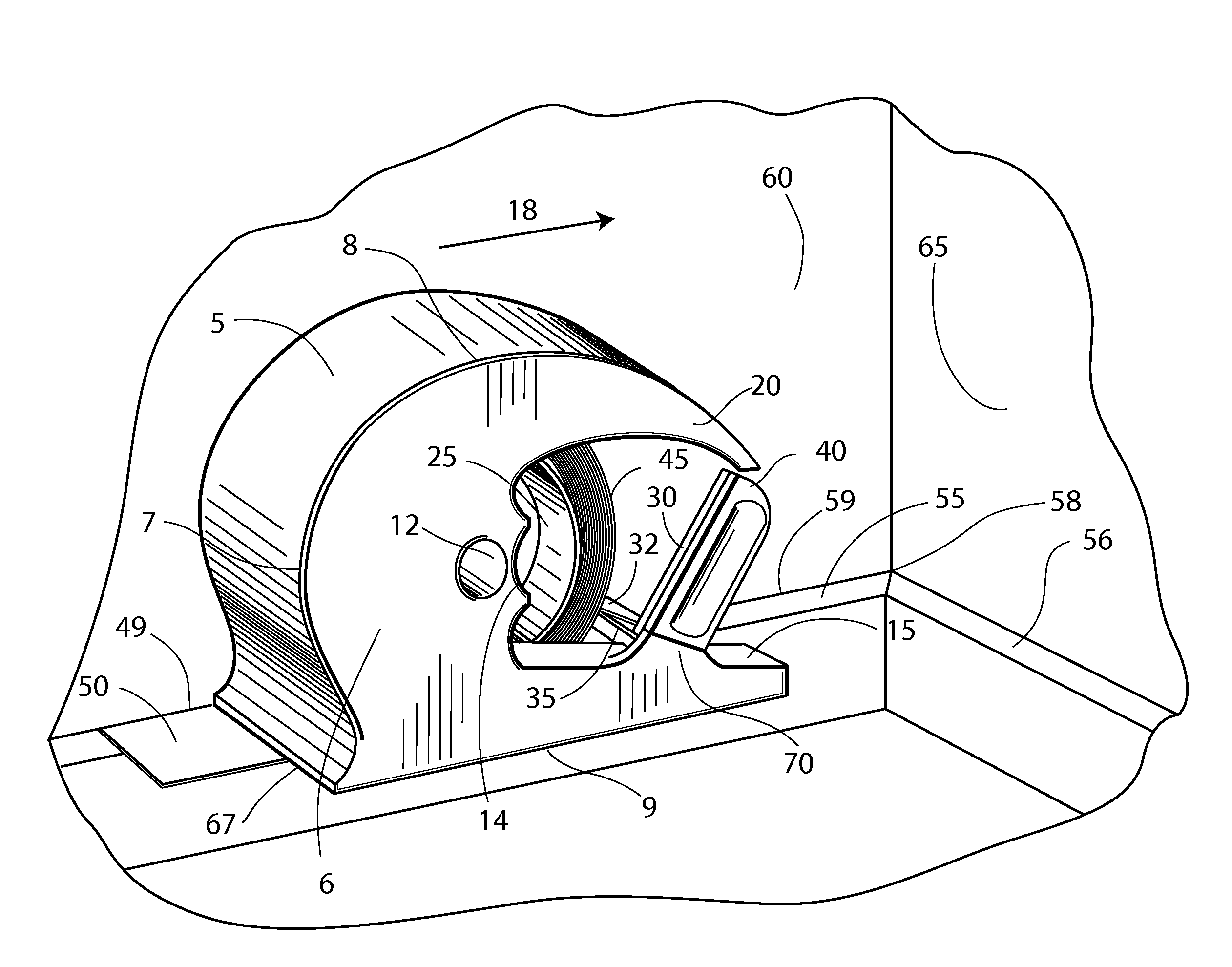
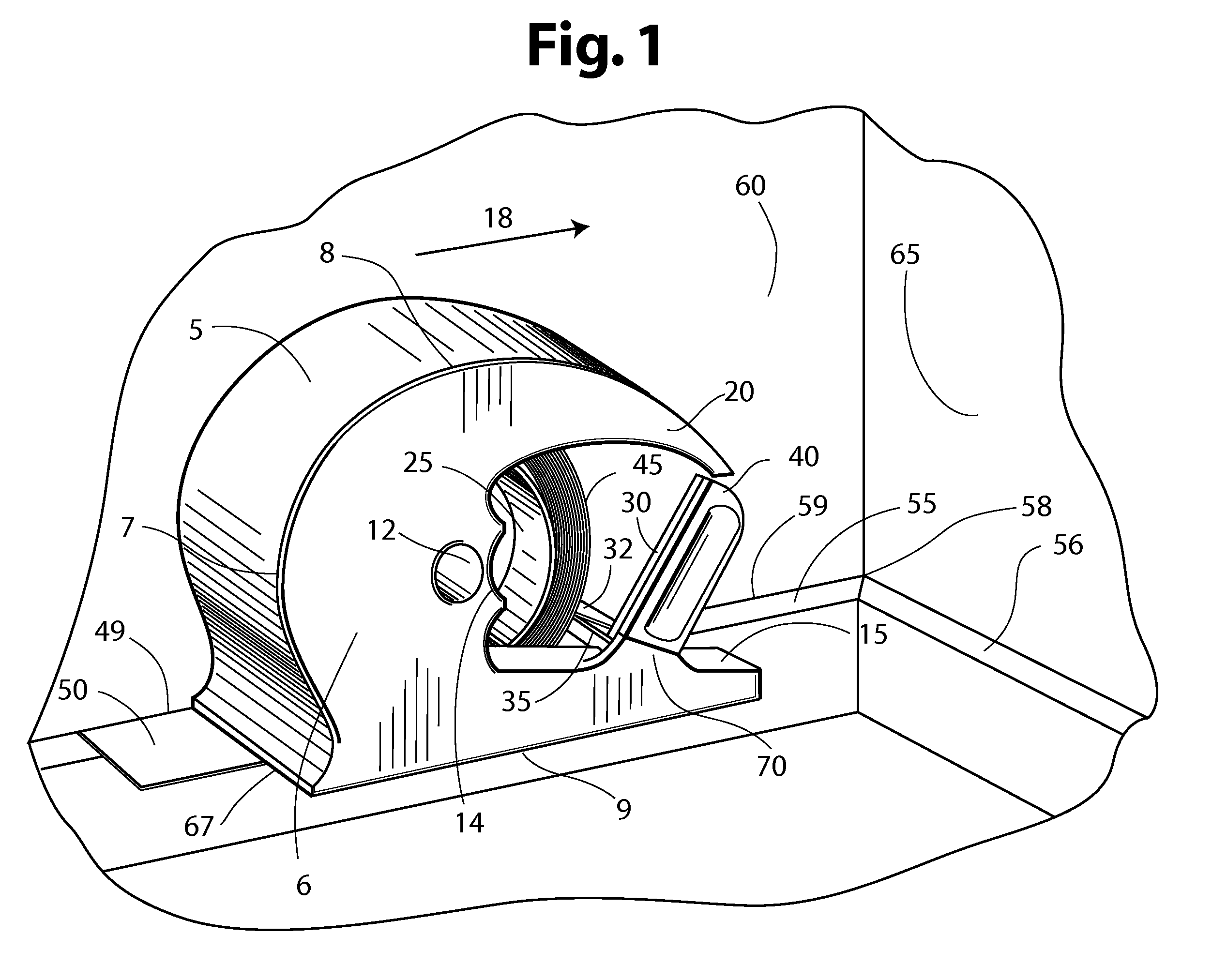
[0021]FIGS. 1 through 4 illustrate a first embodiment of a taping apparatus of the present invention that can be used to manually apply a tape segment 42 along a surface to be protected 55, such as the top of a baseboard 55 or a ceiling 57, with an edge 49 of the tape aligning with an elongate edge 59 at the intersection of the surface to be protected 55 with a surface to be painted or otherwise treated 60 and, when coming to an inside corner 58, the apparatus can cut tape 32 off to the desired length fitting up to a third surface 65 lying substantially orthogonal to the surface to be protected 55 and the surface to be painted 60.

[0022]The taping apparatus of the present invention comprises a tape hub 25, a tape guide roller 41, upper and lower cutting blades 30&35, and a measuring stop 15 all connected to a frame 6. In the preferred embodiment, frame 6 is comprised of a substantially planar body having arcuate upper 8 and rear 7 edges with a peripheral wall 5 extending orthogonally...


PUM

PropertyMeasurementUnit
lengthaaaaaaaaaa
timeaaaaaaaaaa
speedaaaaaaaaaa

Abstract

A tape applicator device that applies tape to a surface edge that is contiguous with a second surface and can also cut the tape to fit precisely up to a third surface that orthogonally intersects the first and second surfaces forming an inside corner like that found at the juncture of two walls and a ceiling. The applicator employs an upper and lower cutting blade and a tape measuring element to precisely measure and cut the tape to the desired length to fit into an inside corner. The tape applicator of the invention also includes a tape roll journaling means and tape guide means to dispense and apply tape to the surface edge.

Description

BACKGROUND [0001]1. Field of the Invention[0002]The present invention relates generally to the field of painting and more particularly, it relates to a taping apparatus having a cylindrical hub for mounting a roll of tape, a secondary arcuate surface for pressing tape down to a surface, and a tape measuring and cutting mechanism, which allows a user to precisely cut the tape to the desired length without requiring the use of additional tools such as a blade or scissors.[0003]2. Description of the Prior Art[0004]A major problem that is encountered when taping the edges of a wall is the difficulty in taping up to the edge quickly and accurately. It is common practice to accomplish this unaided by holding the roll of tape in one's hand while pulling out tape, lining it up to the edge and pressing it down to the surface. This process is time-consuming and difficult to do accurately. Adding to the difficulty, when taping up to an inside corner, a user has to use another tool to cut the t...

Claims


Application Information

Patent Timeline
Patent Type & Authority Applications(United States)
IPC IPC(8): B32B37/00B32B38/00
CPCB65H35/0033Y10T156/1348B65H35/0093
Inventor PYLES, CHRISTOPHER PYLES
Owner PYLES CHRISTOPHER PYLES
Why Eureka
Try Eureka