Transmission inspection three-dimensional flight path automatic planning method based on laser point cloud data
A technology of laser point cloud data and automatic planning, which is applied in the directions of line-of-sight measurement, surveying and navigation, and the use of optical devices. It can solve problems such as high labor intensity, high technical requirements for UAV controllers, and difficult working conditions. The effect of avoiding safety hazards, reducing technical requirements, and improving safety and efficiency
- Summary
- Abstract
- Description
- Claims
- Application Information
AI Technical Summary
Problems solved by technology
Method used
Image
Examples
Embodiment 1
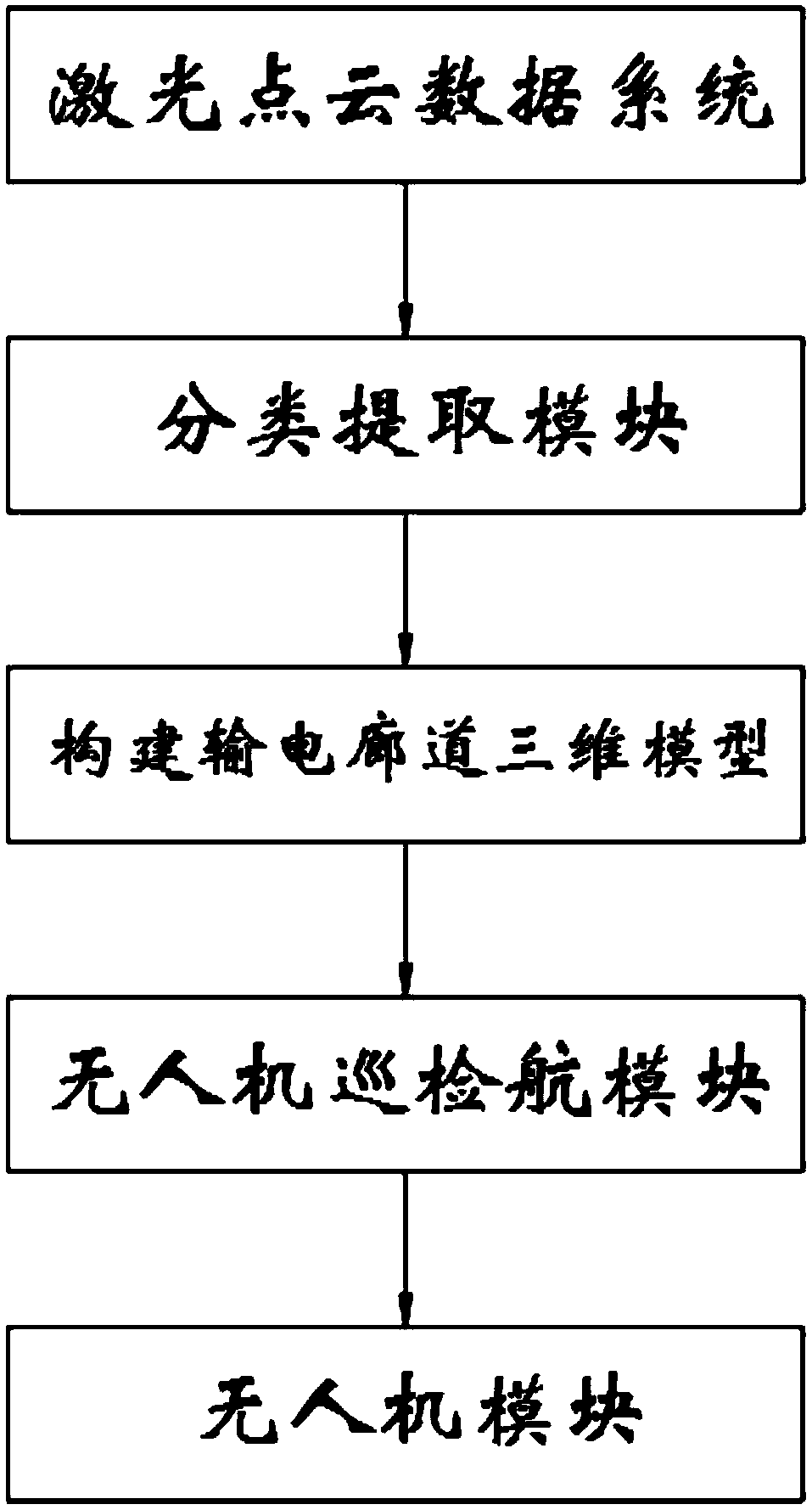
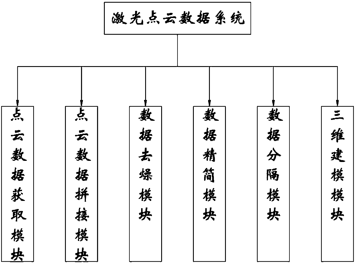
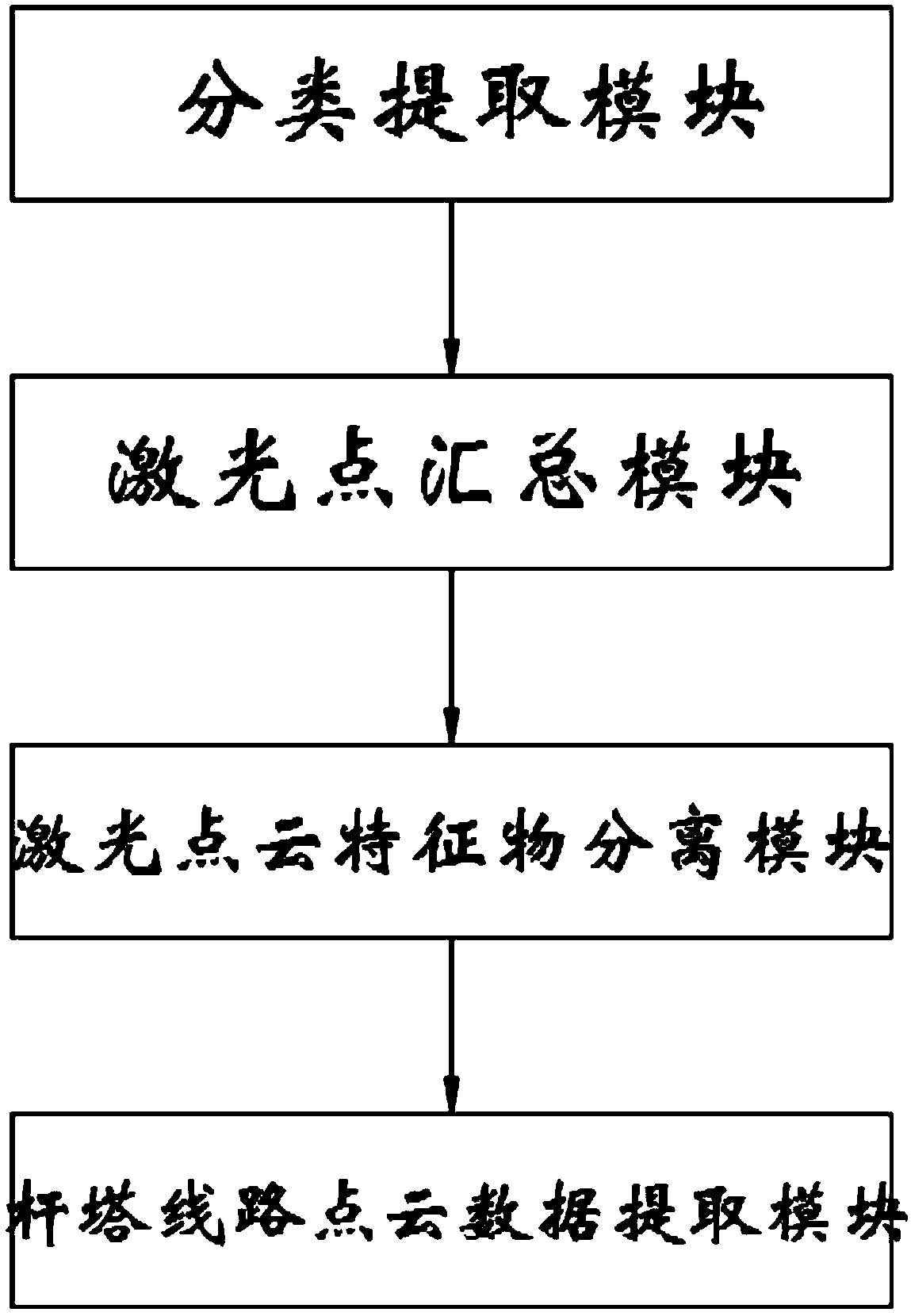
[0048] Automatic planning method of three-dimensional track for power transmission inspection based on laser point cloud data, such as figure 1 and figure 2 As shown, it includes laser point cloud data system, analysis module and UAV module. The scanner obtains the point cloud data of the object in a non-contact manner, models it and truly restores the original appearance of the object; the classification extraction module is used to separate and extract the target; the module of building a 3D model of the transmission corridor is used to establish the transmission corridor The 3D model of the UAV; the UAV inspection track module is used to plan the inspection path of the UAV; the UAV module is used for regular or special inspection work on the transmission line, and the laser point cloud data system includes point cloud data acquisition module, point cloud data splicing module, data de-drying module, data reduction module, data separation module and 3D modeling module, and ...
Embodiment 2
[0068] As the second embodiment of the present invention, compared with Embodiment 1, the difference lies in the splicing module. The splicing module in this embodiment adopts point cloud direct splicing. There must be a certain degree of overlap between them, generally greater than 30%, and there must be more obvious feature points. After the scanning is completed, find the points with the same name in the overlapping area for point cloud stitching.
Embodiment 3
[0070] As the third embodiment of the present invention, compared with Embodiment 1, the difference lies in the splicing module. In this embodiment, the splicing module is control point splicing, and the control point splicing method is as follows: use a three-dimensional laser scanner in combination with a positioning system , first determine the control points in the public area, scan the control points while scanning the object, use the positioning technology to determine the coordinates of the control points, and then register the point cloud data based on the control points.
PUM
 Abstract
Description
Claims
Application Information
 - R&D
- Intellectual Property
- Life Sciences
- Materials
- Tech Scout
- Unparalleled Data Quality
- Higher Quality Content
- 60% Fewer Hallucinations
Browse by: Latest US Patents, China's latest patents, Technical Efficacy Thesaurus, Application Domain, Technology Topic, Popular Technical Reports.
© 2025 PatSnap. All rights reserved.Legal|Privacy policy|Modern Slavery Act Transparency Statement|Sitemap|About US| Contact US: help@patsnap.com


