Motor current shaping

a motor current and current shaping technology, applied in the direction of electrical commutators, control systems, electrical equipment, etc., can solve the problems of em interference, spikes can create audible noise, etc., and achieve the effect of reducing noise during the operation of the motor

Active Publication Date: 2009-04-21
MINEBEAMITSUMI INC
View PDF10 Cites 2 Cited by
  • Summary
  • Abstract
  • Description
  • Claims
  • Application Information

AI Technical Summary

Benefits of technology

[0010]The present invention provides for a method and apparatus for controlling the drive signal that is applied to a coil of a motor during a commutation period. The drive signal comprises a plurality of pulses. For the duration of the commutation period the pulses are varied, and by so doing noise reduction during operation of the motor is achieved. The present invention also provides for noise management by appropriate control of the drive signal during a commutation period when a coil is being energized by the drive signal.

Problems solved by technology

These spikes can create audible noise.
More significantly, the spikes can be a source of EM interference (EMI).

Method used


Image

  • Motor current shaping
  • Motor current shaping
  • Motor current shaping

Examples


Embodiment Construction

[0019]Although the present invention is readily adapted for any brushless DC motor arrangement, Applicant's brushless DC motor fan apparatus will serve as a convenient vehicle for describing a specific illustrative embodiment of the invention. In particular, the motor apparatus disclosed in Applicant's U.S. Pat. No. 6,611,117 will be described herein.

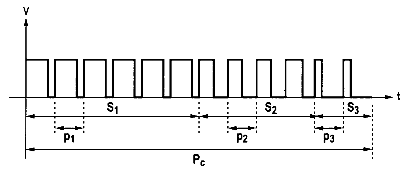
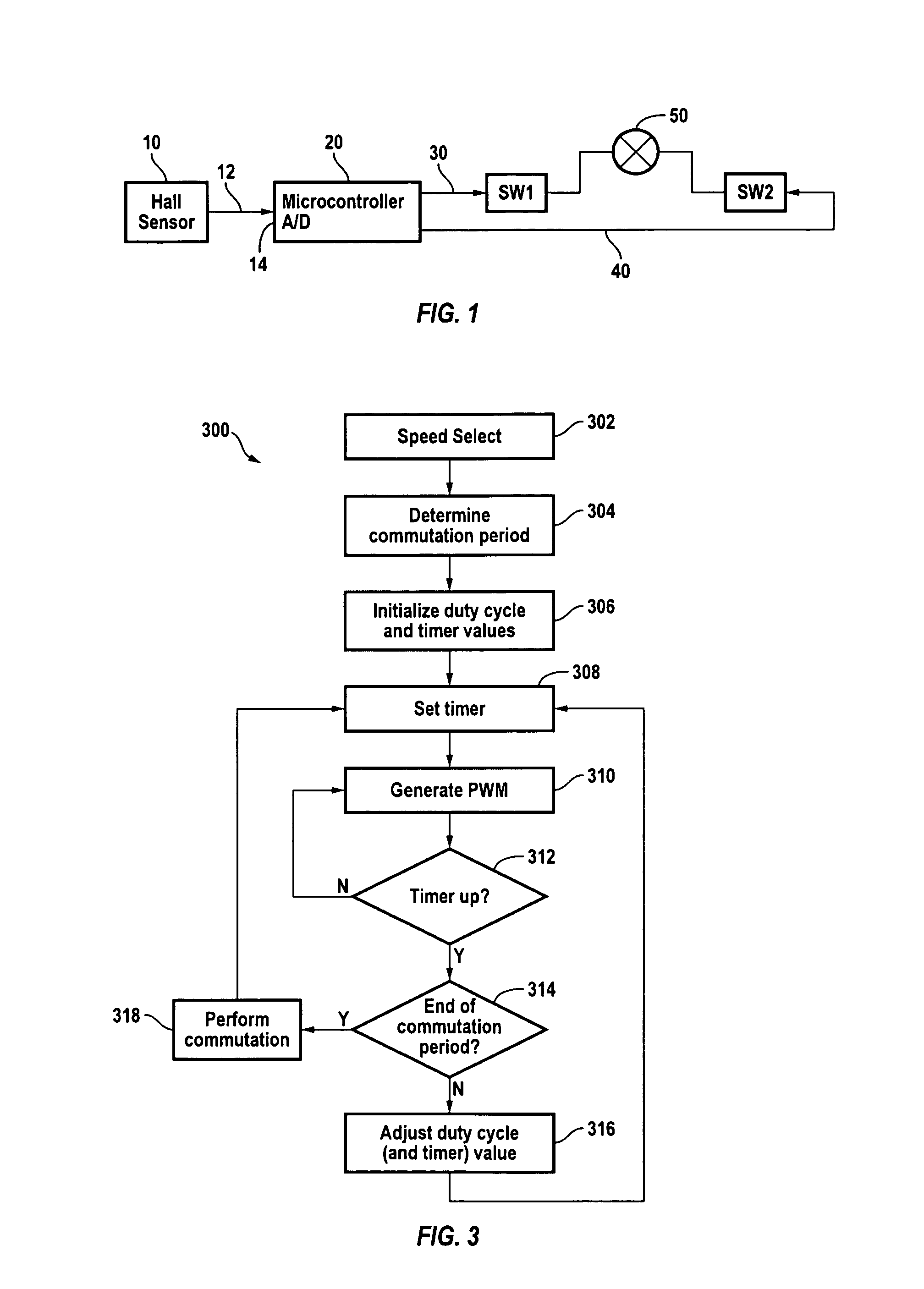
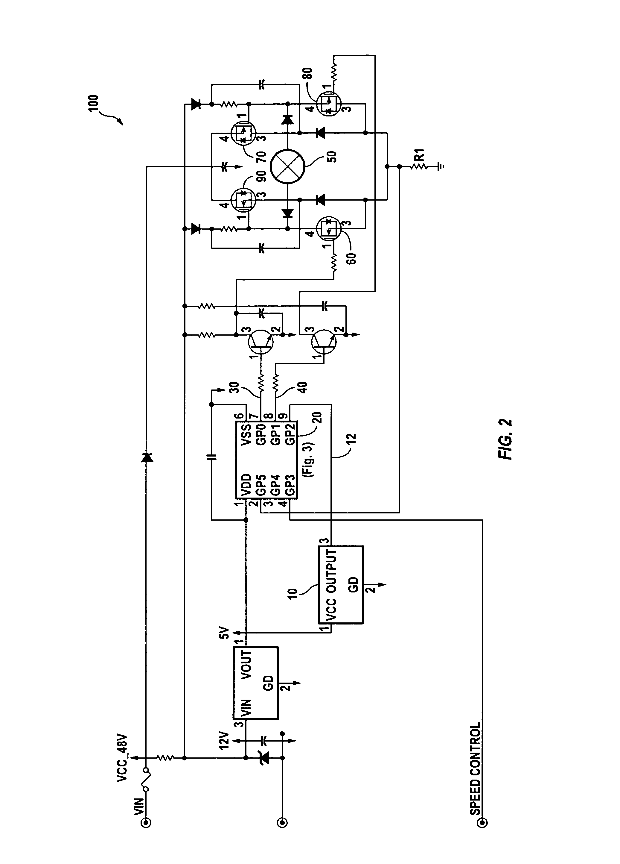
[0020]FIGS. 1 and 2 show a simplified block diagram and a schematic diagram respectively of a brushless DC motor, generally designated 100, according to an embodiment of the present invention. The motor 100 includes a Hall sensor 10 having an output 12; a microcontroller 20 having complementary outputs 30 and 40; stator coil 50; and switches SW1 and SW2. In the block diagram shown in FIG. 1, the switches SW1 and SW2 comprise the two switches that are on at the same time in a full-bridge driver stage. In the schematic diagram shown in FIG. 2, the switches SW1 and SW2 of FIG. 1 are represented by switches 60 and 70 or switches 80 and 90. ...


PUM


Abstract

A method and apparatus is disclosed for generating a drive signal that is applied to a coil in a motor. The drive signal is applied during a period (commutation period) between a commutation event and the immediately following commutation event when the coil is energized. The drive signal comprises pulses which vary over the duration of the commutation period.

Description

CROSS-REFERENCE TO RELATED APPLICATIONS[0001]The present invention is related to the following commonly owned applications: U.S. application No. 09 / 556,717, filed Apr. 21, 2000, now U.S. Pat. No. 6,611,117 issued Aug. 26, 2003 and U.S. application No. 10 / 175,654, filed Jun. 20, 2022, now U.S. Pat. No. 6,801,004 issued Oct. 5, 2004, both of which are herein fully incorporated in their entirety by reference for all purposes.BACKGROUND OF THE INVENTION [0002]The present invention relates generally to electric motors and the management of noise produced during operation of electric motors. More specifically, the present invention relates to noise management in brushless DC (direct current) motors and in particular to shaping the signal for energizing the coils in a brushless DC motor.[0003]The basic construction of a brushless DC motor includes a rotating permanent magnet(s) (the permanent magnet rotor) surrounded by some number of coil windings (stator coils). A current is made to flow...

Claims


Application Information

Patent Timeline
Patent Type & Authority Patents(United States)
IPC IPC(8): H02P25/08
CPCH02P6/10H02P6/14
Inventor OTSUKA, SHUICHIHARDT, ERIC
Owner MINEBEAMITSUMI INC
Why Eureka
Try Eureka