Display device and information terminal device

a technology of information terminal and display device, which is applied in the direction of static indicating device, identification means, instruments, etc., can solve the problems of high cost, high maintenance cost, and complicated structure of conventional display apparatus having the coordinate input function, and achieve the effect of reducing size and price, and high precision

Inactive Publication Date: 2009-04-21
JAPAN DISPLAY CENTRAL CO LTD
View PDF23 Cites 76 Cited by
  • Summary
  • Abstract
  • Description
  • Claims
  • Application Information

AI Technical Summary

Benefits of technology

[0004]In order to solve the above-described problems, the present invention has been achieved. An object of the present invention is to provide a display apparatus and an information terminal apparatus that can be reduced in size and price and that can detect coordinates with a high precision.

Problems solved by technology

However, the conventional display apparatus having the coordinate input function is difficult to reduce in size and often heavy in weight.
Furthermore, as compared with the ordinary display apparatus, the conventional display apparatus having the coordinate input function is considerably high in cost and complicated in structure.
Therefore, there is a problem, such as fragileness, in maintenance.

Method used


Image

  • Display device and information terminal device
  • Display device and information terminal device
  • Display device and information terminal device

Examples


first embodiment

[0043]In a liquid crystal display apparatus according to a first embodiment, a sensor which takes in an image is disposed for each pixel. A substrate having a common electrode formed of a transparent electrode material such as ITO is disposed so as to be opposed to an LCD substrate with a predetermined clearance (approximately 5 microns). A liquid crystal material is injected between the LCD substrate and the opposed substrate, and they are sealed by a predetermined method. In addition, sheet polarizers are stuck on outsides of both substrates and used.

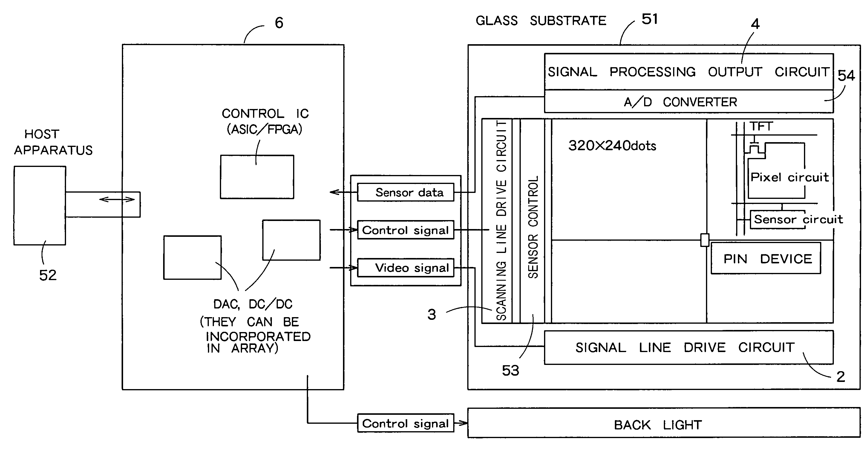
[0044]FIG. 1 is a block diagram showing a schematic configuration of a liquid crystal display apparatus according to one embodiment. The liquid crystal display apparatus shown in FIG. 1 includes a pixel array unit 1 having signal lines and scanning lines arranged in a matrix form, a signal line drive circuit 2 which drives the signal lines, a scanning line drive circuit 3 which drives the scanning lines, a signal processing output cir...

second embodiment

[0101]In a second embodiment, coordinate detection of the finger is conducted on the basis of a difference image between two images picked up consecutively.

[0102]FIG. 12 is a flow chart showing a coordinate detection processing of the finger conducted by the signal processing output circuit 4 or the controller 6. FIG. 13 is a diagram showing an example of a picked-up image. First, image pickup corresponding to one frame is conducted with the back light lit. A result of the image pickup (hereafter referred to as first image) is stored in a storage not shown (step S11).

[0103]As shown in FIG. 13(a), the picked-up image contains a white portion generated by noise light regardless of whether the back light is lit. In the state in which the back light is lit, an image containing a white portion generated by the finger and a white portion generated by noise light is obtained as shown in FIG. 13(b).

[0104]Subsequently, image pickup corresponding to one frame is conducted with the back light ...

third embodiment

[0115]In the above-described second embodiment, the example in which the back light is turned on / off in the finger coordinate detection period has been described. However, the difference image may also be detected by changing the color of the whole pixel array unit 1 while continuously turning on the back light.

[0116]More specifically, in the finger coordinate detection period, black is displayed on the whole pixel array unit 1 each time image pickup corresponding to one frame is conducted. And a difference image is detected as a difference between an image picked up when black is displayed and an image picked up when black is not displayed. If black is displayed on the whole pixel array unit 1, light from the pixel array unit 1 is not applied to the bulb of the finger and reflected light from the bulb of the finger is not input to sensors. Accordingly, finger coordinate detection becomes possible in the same way as the second embodiment.

[0117]Thus, in the third embodiment, it is no...


PUM

PropertyMeasurementUnit
thicknessaaaaaaaaaa
frequencyaaaaaaaaaa
frequencyaaaaaaaaaa

Abstract

A liquid crystal display apparatus according to the present invention includes a pixel array unit 1 having signal lines and scanning lines respectively arranged side by side, a signal line drive circuit 2 which drives the signal lines, a scanning line drive circuit 3 which drives the scanning lines, a signal processing output circuit 4 which serially outputs the picked-up image data supplied from the sensors, and a sync signal generation circuit 5. A black-white change obtained in the picked-up image data when a finger is brought close to or brought into contact with the pixel array unit 1 is detected, and the coordinate position of the finger is identified taking the ambient brightness into consideration. Regardless of whether the surroundings are bright or dark, therefore, the coordinate position can be detected with high precision. Furthermore, when conducting the coordinate detection, the picked-up image data corresponding to all pixels are not detected, but the picked-up image data are detected every a plurality of pixels in both the signal line direction and the scanning line direction. Therefore, the time taken to detect the coordinates can be shortened.

Description

TECHNICAL FIELD[0001]The present invention relates to a display apparatus and an information terminal apparatus having a function of taking in an image.BACKGROUND ART[0002]A technique of providing a display apparatus itself with a coordinate input function instead of providing a coordinate pointing member such as a mouse is proposed. For example, a configuration having a pressure sensitive touch panel disposed on a surface of the display apparatus, and a configuration having an electromagnetic induction tablet disposed on a back of the display apparatus are known. In the pressure sensitive touch panel, two transparent flat plates on which transparent electrode patterns made of a transparent electrode material are formed are opposed to each other with a predetermined clearance between them. Only in a portion pressed by a finger or the like, the electrode patterns are brought into contact with each other. As a result, resistance values in the electrode patterns are changed, and coordi...

Claims


Application Information

Patent Timeline
Patent Type & Authority Patents(United States)
IPC IPC(8): G09G3/36G06F3/042G02F1/13357G02F1/133G02F1/1368G06F3/041G06T1/00G09F9/00G09G3/20G09G3/34
CPCG06F3/0421G06F3/0412G02F1/13338G06F3/04166G06F3/0304G02F1/1368G09G3/36
Inventor NAKAMURA, TAKASHIYOSHIDAHAYASHI, HIROTAKAISHIKAWA, MIYUKITANAKA, YASUHARU
Owner JAPAN DISPLAY CENTRAL CO LTD
Why Eureka
Try Eureka