Decoding apparatus using tool information for constructing a decoding algorithm

a decoding algorithm and tool information technology, applied in the field of decoding apparatus, can solve the problems of large image information, inability to decode data itself, and large scale of the decoding device, and achieve the effect of efficiently and quickly performing the decoding operation

Inactive Publication Date: 2007-03-20
DOLBY LAB LICENSING CORP
View PDF24 Cites 0 Cited by
  • Summary
  • Abstract
  • Description
  • Claims
  • Application Information

AI Technical Summary

Benefits of technology

[0046]The present invention has been achieved in view of the above problems. It is therefore an object of the invention to provide a coding and decoding apparatus which can select the most suitable tools based on the comparison with the tool-correspondent information and can perform the decoding operation efficiently and quickly when the received coded data is decoded using the tools simultaneously received.
[0047]It is another object of the invention to provide a coding and decoding apparatus which is able to decode the coded data even if the coding capacity of the coding tools on the coding side is not in agreement with the decoding capacity of the decoding tools on the decoding side so that the apparatus on the decoding side can be reduced in size and price.
[0048]It is a further object of the invention to provide a coding and decoding apparatus in which, by transmitting only the differential information as to the functional tool and the decoding scheme which are already prepared in the decoding apparatus when the decoding scheme is transmitted, it is possible to designate and identify the necessary decoding scheme with fewer steps, so that the efficiency in the use of the communication line will not be deteriorated critically.

Problems solved by technology

In general, in the case where image information as in the video phone or video conference system is transmitted, the amount of image information is very large.
However, this method needs a dedicated device with software for each of the tools, thus the scale of the decoder tends to become large.
To make matters worse, if the decoder receives the data which has been processed by a tool that is not provided for the decoder, it is impossible to decode the data itself.
In the case where the capacity of the decoding apparatus for processing a certain algorithm is lower than the total processing capacity for all the tools constituting the algorithm requested by the coder side, even if the tools transmitted from the coder is stored at the decoder side, the received data cannot be decoded exactly due to the inferior processing capacity of the decoder side.
Also in the conventional coding and decoding apparatus, when the tools which were used in the coder side are compared to the tools which are stored at the decoder side, the tools themselves should be compared to each other; this process required a very long period of time.
If these tools on the decoder side do not have the processing capacities for the tools on the coder side, the coded data cannot be decoded, thus making it impossible to establish the communication.
However, if the divided number of pixels in the frame predictive coding is dissimilar (or the frame predictive coding tools are different), the structure of the coded data becomes quite different and thus it becomes impossible to interchange the coded data.
Therefore, when the processing capacity for the decoding tool is not in agreement with that for the coding tool, it is totally impossible to decode the coded data received.
Therefore, the device is increased in size and cost.
Further, the usage will be limited if the system has only limited types of coding schemes previously equipped, as stated above.
That is, even when the coding scheme is not much different from the decoding scheme that is previously provided, the communication may require a large transmission rate, thus possibly reducing the efficiency in the use of the line.
However, in the aforementioned coding and decoding system of the conventional scheme, the communication can be performed based only on the limited kinds of coding and decoding algorithms.
However, if all the tools are provided to deal with all the algorithms, the hardware and software becomes bulky, and the apparatus will increase in cost and inevitably becomes large.
On the other hand, if the apparatus is reduced in cost and size and therefore the apparatus does not have adequate capacities, the risk of the failure to perform communications becomes high.
Therefore, the delay before the start of transmission to the decoding of the coded data becomes long.
That is, the delay before the start of transmission to the decoding of the coded data becomes long and therefore it is impossible to make use of the merit from the hierarchical structure of the tools.

Method used


Image

  • Decoding apparatus using tool information for constructing a decoding algorithm
  • Decoding apparatus using tool information for constructing a decoding algorithm
  • Decoding apparatus using tool information for constructing a decoding algorithm

Examples


first embodiment

(First Embodiment)

[0115]FIG. 11 is a block diagram showing the first embodiment of a coding and decoding apparatus in accordance with the invention. This coding and decoding apparatus includes a controller 11a, a coder 12a, a response controller 13a, a decoder 14a, a tool storage controller 15a, a tool storage section 16a, a coding capacity storing section 17a, a decoding capacity storing section 18a and a capacity comparator 19a.

[0116]Controller 11a is a unit for controlling the entire apparatus. The total amount of the processing capacities for the tools in decoder 14a which constitute the algorithm is stored previously in decoding capacity storing section 18a as a decoding capacity. The processing capacity for each tool in decoder 14a is represented numerically. Coder 12a transmits each tool together with its numerical processing capacity required for the tool to the other terminal device.

[0117]Here, the capacity for a tool is represented numerically by selecting a standard oper...

second embodiment

(Second Embodiment)

[0129]Table 2 shows an example of the control of tools in the second embodiment of a coding and decoding apparatus in accordance with the invention. As shown in Table 2, each tool is allotted with a unique key. For example, a tool for motion compensation with integer-pixel precision is assigned with a key Aa01. In the same manner, all the tools are allotted with corresponding keys so that each tool can be discriminated.

[0130]FIG. 13 shows an example of the key assignment. For instance, the key has a capital alphabetical character for broad classification (motion compensated prediction, DCT, etc.), a lowercase alphabetical character for subdivision (integer-pixel precision, half-pixel precision, etc.) and two digit numerals for version.

[0131]

TABLE 2KeyToolAa01Integer-pixel precisionmotion compensationAb01Half-pixel precisionmotion compensationBa01DCTBb01Wavelet transformCa01Linear quantizationCb01Vector quantization

[0132]FIG. 14 is a block diagram showing a coding ...

third embodiment

(Third Embodiment)

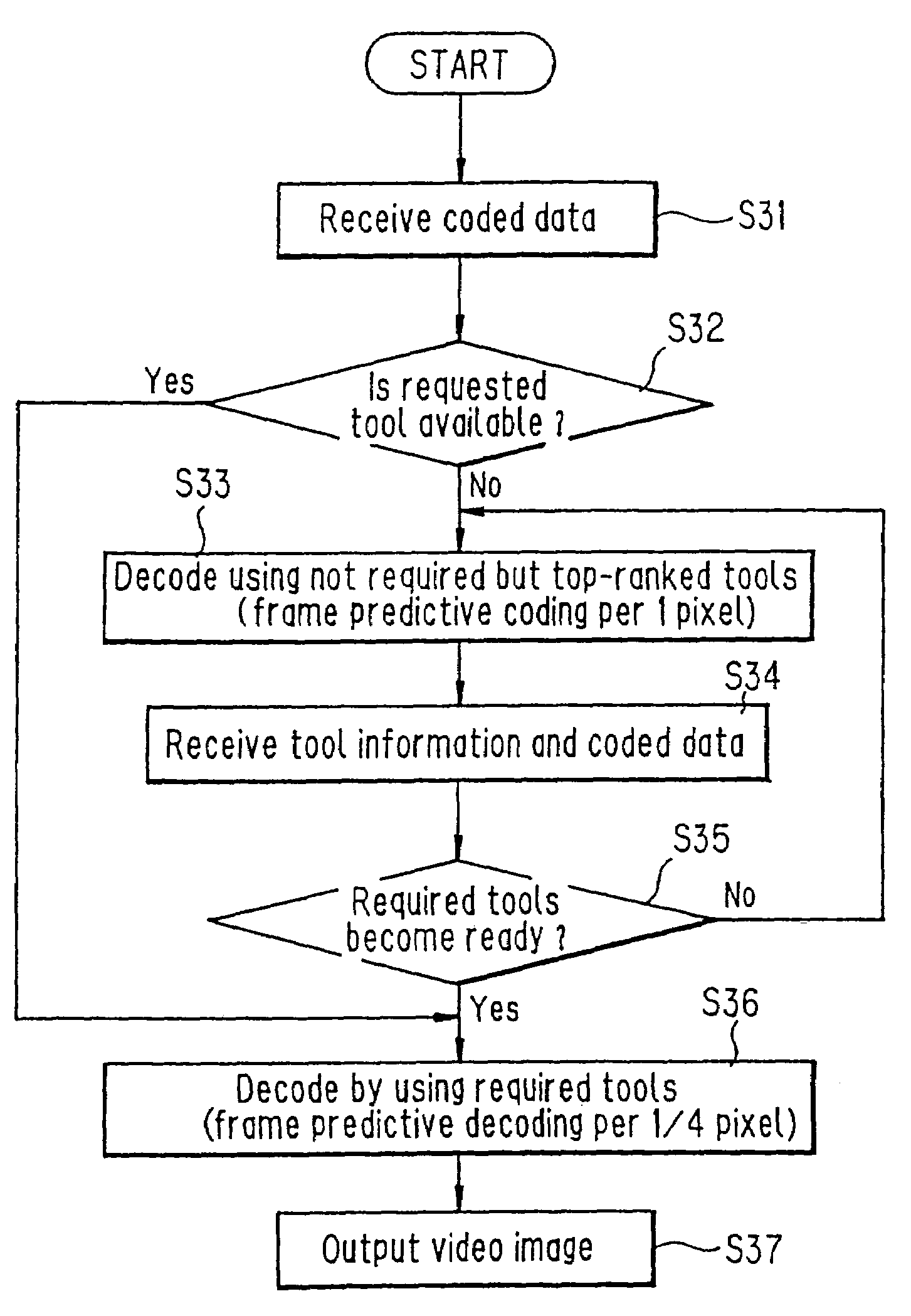
[0143]In reference to drawings, description will be made of a coding and decoding apparatus of the third embodiment of the invention hereinbelow in which a video signal is sampled per ¼ pixel by the frame predictive coding so that the coded data is transmitted and the transmitted data is decoded.

[0144]FIG. 18 is a system block diagram showing the configuration of an overall transmitting and receiving system to which a coding and decoding apparatus of the invention is applied. A transmitting system la shown in the figure includes: a video input unit 101 converting video information inputting through unillustrated visual sensor into a video signal; a coding apparatus 102 coding the inputted video signal from the video input unit 101 to produce coded data; a transmitter 103 outputting the coded data produced by coding apparatus 102 onto a communication net 300.

[0145]Here, coding apparatus 102 is composed of: a transformer 121 receiving the video signal and subjecting ...


PUM


Abstract

A coding and decoding apparatus is constructed so that the coding side transmits coded data together with identifying information for identifying the device of decoding the coded data, and the decoding side is capable of storing a number of decoding schemes so as to perform decoding based on one of the previously stored schemes. The apparatus further has devices for storing the received tools and tool-correspondent information which numerically represents the capacities of the tools so that it can make a comparison between the decoding capacity and the processing capacities of the tools to determine the possibility of the operations of the received tools. Further, a set of the tools are hierarchized so that the coded data produced by the n-ranked tool can be decoded by the (n+1)-ranked tool. Alternatively, the tools are defined in a hierarchical manner so that the decoding tools installed in the decoding apparatus will be able to assure the minimum quality and the requested decoding process can be performed by the received decoding tool. Further, the identification code of the decoding scheme used can be transmitted as required so that the decoding scheme can be expanded by transmitting the differential information from the basic decoding scheme.

Description

[0001]This application is a Divisional of co-pending U.S. Pat. application Ser. No. 09 / 407,880, filed on Sep. 29, 1999 and issued as U.S. Pat. No. 6,687,409 on Feb. 3, 2004, which is a Divisional of prior U.S. Pat. application Ser. No. 08 / 727,787, filed on Oct. 8, 1996 and issued as U.S. Pat. No. 5,987,181 on Nov. 16, 1999, the entire contents of which are hereby incorporated by reference and for which priority is claimed under 35 U.S.C. § 120; and this application claims priority of Application Nos. 7-264127 filed in Japan on Oct. 12, 1995; 7-277463 filed in Japan on Oct. 25, 1995; 7-308915 filed in Japan on Nov. 28, 1995; and 7-310667 filed in Japan on Nov. 29, 1995 under 35 U.S.C. § 119.BACKGROUND OF THE INVENTION[0002](1) Field of the Invention[0003]The present invention relates to a coding and decoding apparatus for coding information such as an image signal etc. to transmit it and decoding the coded data. More detailedly, the present invention relates to a coding and decoding ...

Claims


Application Information

Patent Timeline
Patent Type & Authority Patents(United States)
IPC IPC(8): G06K9/36H04N7/24H04N7/26H04N7/36H04N7/50
CPCH04N21/235H04N19/523H04N21/2662H04N21/435H04N21/4621H04N21/8166H04N21/8193H04N19/00H04N19/70H04N19/46H04N19/51H04N19/61H04N19/12H04N19/156H04N19/164H04N19/44H04N19/82H04N21/25808H04N21/25858
Inventor MAKIYAMA, TAKESHISATO, SEIJIKOIZUMI, NORITAKAUCHIUMI, TADASHI
Owner DOLBY LAB LICENSING CORP
Why Eureka
Try Eureka