Dryness/wetness responsive sensor having first and second wires spaced 5 nm to less than 20 μm apart

a sensor and dryness technology, applied in the field of high-speed response/high-sensitivity dryness/wetness responsive sensor, can solve the problems of large aging variation, inability to use humidity sensors of the electric resistance type in low humidity environments of 10% rh or less and in high humidity environments of over 90% rh, etc., to achieve simple structure, reduce size and price, and high sensitivity

Active Publication Date: 2019-04-23
NAT INST FOR MATERIALS SCI
View PDF43 Cites 0 Cited by
  • Summary
  • Abstract
  • Description
  • Claims
  • Application Information

AI Technical Summary

Benefits of technology

[0023]According to the present invention, since a dryness / wetness responsive sensor of high sensitivity and high-speed responsiveness is provided that has a simple structure and needs no sensor driving power, the dryness / wetness responsive sensor can be reduced in size and price.

Problems solved by technology

However, if the humidity sensor of the electric resistance type gets wet with water, the sensor element will break down, and thus, the humidity sensor of the electric resistance type cannot be used under a condition in which dew condensation may occur.
For this reason, the measurement humidity range is restricted to the range of 10 to 90% RH, and it is difficult to use the humidity sensor of the electric resistance type in a low humidity environment of 10% RH or less and in a high humidity environment of over 90% RH.
In addition, the humidity sensor of the electric resistance type has a large aging variation, and, since it also has high temperature dependency in many cases, a temperature correction is required.
Furthermore, the humidity sensor of the electric resistance type also has problems of large variation in precision (about ±5 to 15% RH) and a long response time (30 seconds to several minutes or even more).
In addition, the humidity sensor of the electrostatic capacitance type also has a problem of higher production cost than that of the humidity sensor of the electric resistance type.
In addition, a conventional humidity sensor cannot detect the size of water droplets attached to the surface of the sensor element due to its sensor structure or its detection principle.
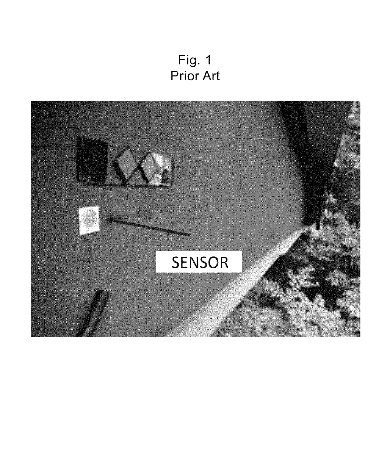
However, since it is difficult and takes a cost to perform an inspection of the degree of corrosion of a steel member itself configuring a structure on site, technique has been developed actually in which corrosion environment sensors are attached to respective places for evaluating their corrosion environments and the degree of corrosion of a steel member are estimated and predicted based on the evaluation results For example, as illustrated in FIG. 1, the degradation of the steel member of a bridge or the like was predicted by attaching a sensor of this type to the steel member and monitoring the corrosion environment at that place.
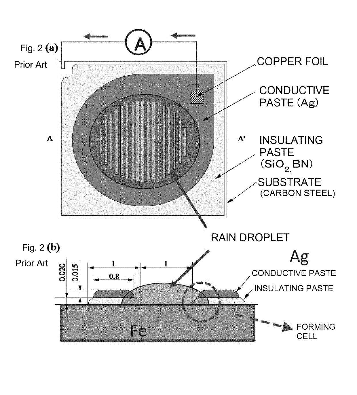
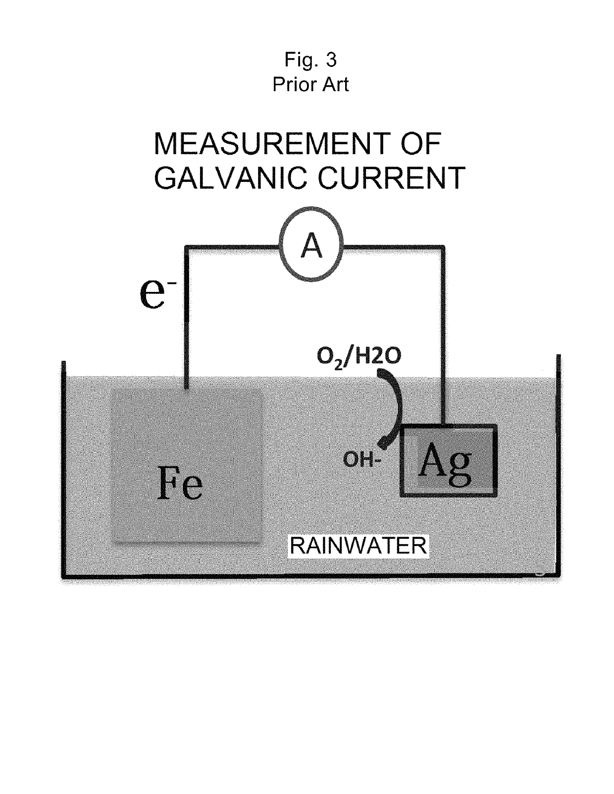
However, since the size of the conventional galvanic sensor becomes larger for compensating for its low sensitivity, it has problems of inconvenience of the handling and high price.

Method used


Image

  • Dryness/wetness responsive sensor having first and second wires spaced 5 nm to less than 20 μm apart
  • Dryness/wetness responsive sensor having first and second wires spaced 5 nm to less than 20 μm apart
  • Dryness/wetness responsive sensor having first and second wires spaced 5 nm to less than 20 μm apart

Examples


examples

[0060]Hereinafter, an embodiment will be described in which a dryness / wetness responsive sensor of which the sensitivity per unit area of the sensor area is improved by employing a simple structure by arranging two electrodes in a comb shape. It is understood that the present invention is not limited to such a specific form, and it should be noted that the technical scope of the present invention is defined by claims.

[0061]FIG. 6 illustrates the embodiment of a structure of the major portion, in other words, an electrode arrangement structure of the dryness / wetness responsive sensor in which an anode electrode of a metal such as iron and a cathode electrode of a metal different from the above-described metal such as silver are arranged in a comb shape on an insulating substrate. As the insulating substrate, for example, a silicon wafer having a silicon oxide film can be used. As examples of a material that can be used for the cathode electrode include gold, platinum, silver, titaniu...


PUM

PropertyMeasurementUnit
RHaaaaaaaaaa
RHaaaaaaaaaa
RHaaaaaaaaaa

Abstract

A dryness / wetness responsive sensor having decreased size, and improved sensitivity and responsiveness. The present invention comprises a thin wire of a first metal and a thin wire of a second metal, which is different from the first metal, wherein the thin wires run in juxtaposition with each other on an insulating substrate, and wherein the spacing between the first thin wire and the second thin wire is in the range of 5 nm or more and less than 20 μm.

Description

TECHNICAL FIELD[0001]The present invention relates to a high-speed response / high-sensitivity dryness / wetness responsive sensor and, more particularly, to a dryness / wetness responsive sensor that has an appropriate structure for decreasing the size and increasing the sensitivity and realizes a high-speed response.BACKGROUND ART[0002]Conventionally, as dryness / wetness responsive sensors, humidity sensors are known which detect humidity based on a change in the electric resistance value (impedance) or electrostatic capacitance of a sensor element (dryness / wetness responsive part). In a humidity sensor of an electric resistance type, as a dryness / wetness responsive material of a sensor element, a polymer, ceramics, or the like is generally used, and since the material is low-cost and the structure is simple, a low cost can be achieved through mass production. However, if the humidity sensor of the electric resistance type gets wet with water, the sensor element will break down, and thus...

Claims


Application Information

Patent Timeline
Patent Type & Authority Patents(United States)
IPC IPC(8): G01N27/04G01N17/04G01N27/12G01N27/22G01N17/00
CPCG01N27/048G01N17/04G01N27/045G01N27/121G01N27/223G01N17/00G01N27/4035
Inventor KAWAKITA, JINSHINOHARA, TADASHICHIKYO, TOYOHIRONABATAME, TOSHIHIDEOHI, AKIHIKOOHKI, TOMOKO
Owner NAT INST FOR MATERIALS SCI
Why Eureka
Try Eureka