
Intumescent firestopping apparatus and method

a firestopping apparatus and intumescent technology, applied in the field of apparatus, can solve the problems of exacerbated problems, difficult installation, adjacent sleeves are difficult to handle, and can slip out of alignment, and achieve the effect of facilitating the installation of a plurality of sleeves

Active Publication Date: 2009-04-28
SPECIFIED TECH
View PDF16 Cites 26 Cited by
  • Summary
  • Abstract
  • Description
  • Claims
  • Application Information

AI Technical Summary

Benefits of technology

"The present invention is a system for adjusting the size of a confinement area to accommodate different sizes of penetrating members and sealing the opening through a construction barrier against the passage of fire. The system includes a sleeve that provides an access corridor through the construction barrier for the penetrating members, intumescent pads that seal tightly around the penetrating members, and a mechanism for adjusting the size of the confinement area by movement of the intumescent pads. The system also includes a securing mechanism for aligning and securing together adjacent sleeves."

Problems solved by technology

However, the presence of an opening through such barriers raises a potential hazard in that a fire can use those opening to pass through the construction barrier, which of itself is an effective fire barrier, and the fire can then spread to adjoining areas of the building.
In addition, there is a further problem in the installation of the subject barriers in that currently where a plurality of such barriers are installed together, such as the sleeves of the Stahl, Sr.
'481 patent, the installation is difficult since the sleeves are normally simply squeezed together and held therein by a wall flange or frame and, in practice, the adjacent sleeves are difficult to handle and can slip out of alignment.
The problem is exacerbated when the installation of the plurality of sleeves is through a floor where gravity is basically working against the installation of the ganged sleeves.

Method used


Image

  • Intumescent firestopping apparatus and method
  • Intumescent firestopping apparatus and method
  • Intumescent firestopping apparatus and method

Examples


Embodiment Construction

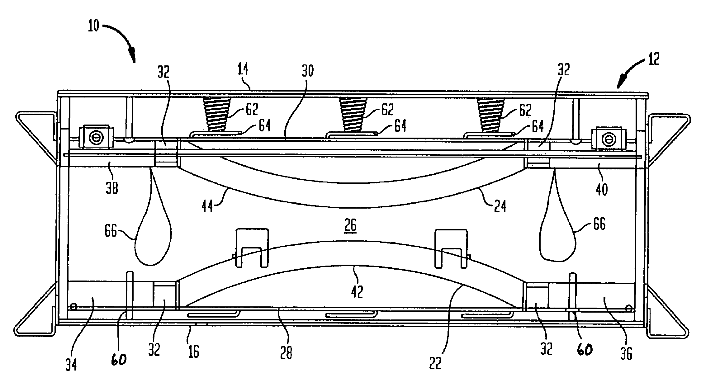
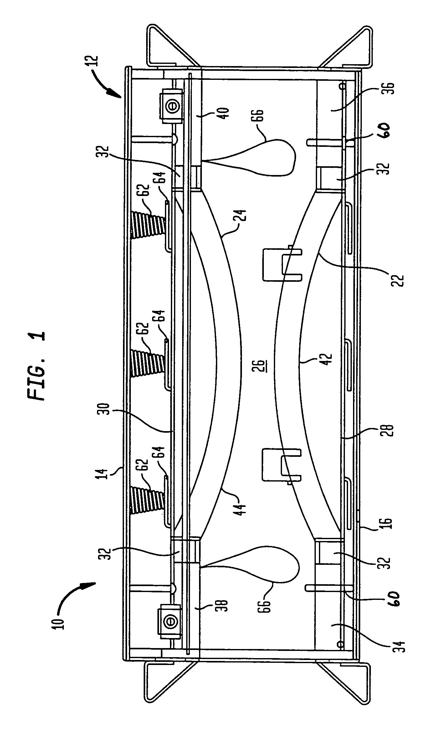
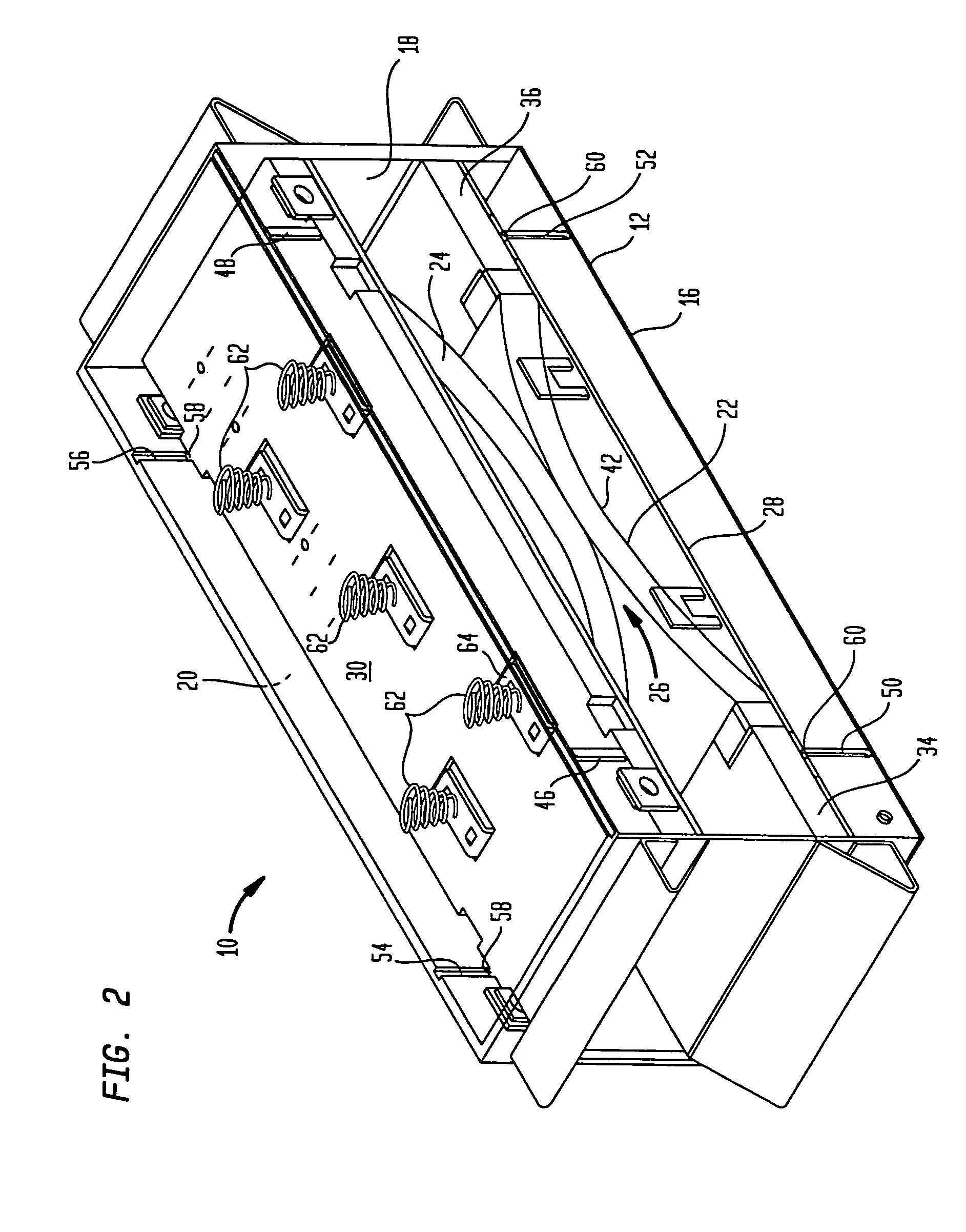
[0023]In FIGS. 1 and 2, there is shown a side schematic view and a perspective schematic view, respectively, of an intumescent firestopping apparatus 10 constructed in accordance with one embodiment of the present invention. As can be seen, the apparatus 10 includes a sleeve 12 that is designed to fit into and pass through an opening in the construction barrier and be fixed therein in the manner as shown and described in the aforementioned Stahl, Sr. U.S. Pat. No. 6,732,481, thereby providing an access corridor through the construction barrier.

[0024]The sleeve 12 is defined by a plurality or exterior walls, and, as shown, there can be seen a top wall 14, a bottom wall 16 and side walls 18, 20 and, in the exemplary embodiment, the top and bottom walls 14, 16 and the side walls 18, 20 are disposed in parallel planes to each other. As described herein, the reference to a top and bottom wall is simply for purposes of explaining the invention, it being seen that the sleeve 12 could be or...


PUM


Abstract

A firestopping apparatus for providing a fire barrier in a construction barrier. The apparatus is comprised of a sleeve within which there are located intumescent pads that are oriented to form a confinement area therebetween to accommodate various penetrating members such as cables, conduits and the like that need to pass through the barrier. Upon sensing the heat from a fire, the intumescent pads seal around the penetrating members to prevent the fire from passing through the barrier. One or both of the intumescent pads is movable toward or away from the other so that the confinement area can be adjusted in size, that is, the confinement area can be increased in size to accommodate a large number of penetrating members of decreased to accommodate a lesser number. One or both of the intumescent pads may be biased in the direction toward decreasing the size of the confinement area.

Description

FIELD OF THE INVENTION[0001]The invention generally relates to apparatus for providing a firestop within a construction opening and, more particularly, to a firestopping apparatus having intumescent pads that form a confinement area therebetween through which penetrating members can pass through the construction opening.BACKGROUND OF THE INVENTION[0002]It is commonplace in the construction and renovation of commercial and residential buildings for the need to pass cables, conduits and the like through construction barriers such as walls, floors ceilings. However, the presence of an opening through such barriers raises a potential hazard in that a fire can use those opening to pass through the construction barrier, which of itself is an effective fire barrier, and the fire can then spread to adjoining areas of the building. As such, fire barriers are normally located with the openings that are designed to prevent the passage of fire through those openings.[0003]One such apparatus for...

Claims


Application Information

Patent Timeline
Patent Type & Authority Patents(United States)
IPC IPC(8): E04C2/52E04B1/94E04C2/00
CPCA62C2/065F16L5/04
Inventor STAHL, SR., JAMES P.
Owner SPECIFIED TECH
Learn More