
Method for monitoring the state of turbines based on their coasting time

a technology of turbines and coasting time, applied in the direction of instruments, testing/monitoring control systems, process and machine control, etc., can solve the problems of fluctuation of around 5% to 10% in the measured coasting tim

Inactive Publication Date: 2009-04-28
SIEMENS AG
View PDF5 Cites 4 Cited by
  • Summary
  • Abstract
  • Description
  • Claims
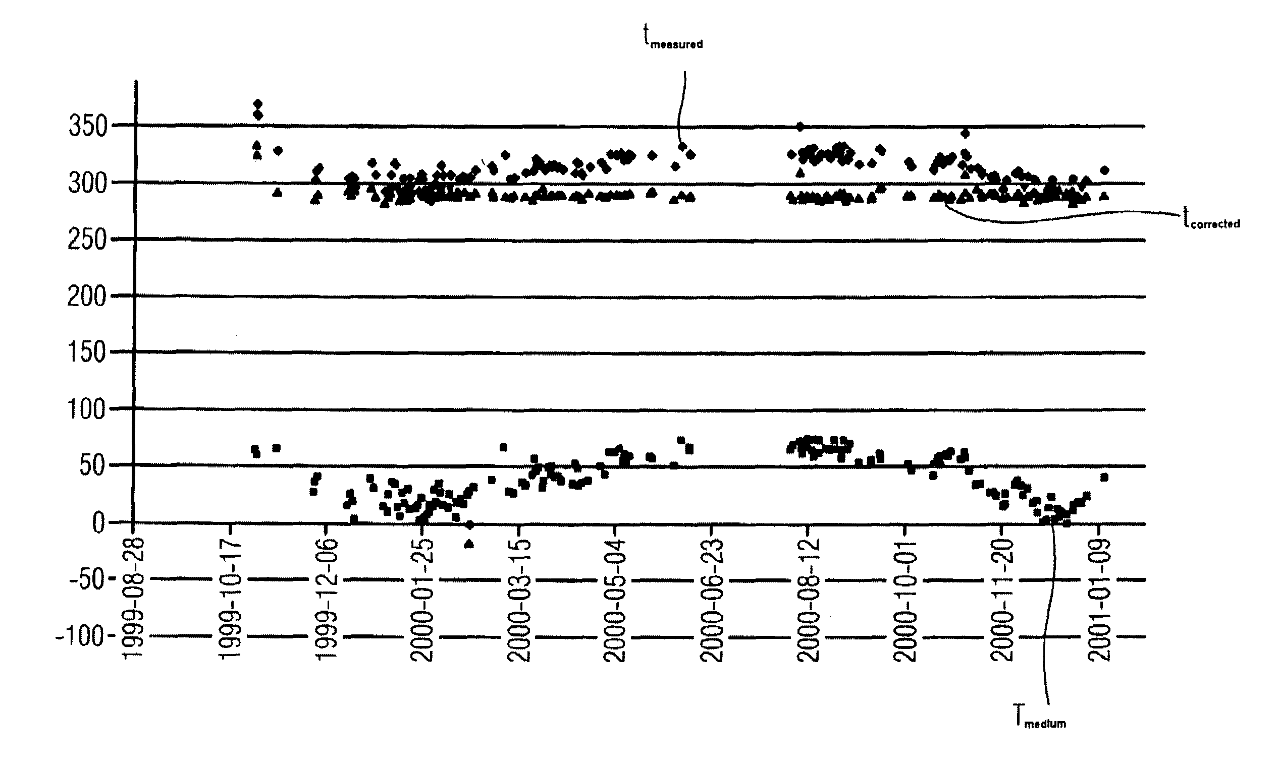
  • Application Information

AI Technical Summary

Benefits of technology

[0009]The advantages achieved with the invention consist in particular of the fact that a significant reduction can be achieved in the fluctuation range of the determined coasting time with very little resource outlay. The temperature of the medium in the turbine is either available in any case as an operational measurement or is relatively simple to measure.
[0010]By correcting the measured coasting time using the temperature of the medium, which represents a manner of normalizing the coasting time with temperature, it is possible to reduce the fluctuation range of the determined coasting time from around 5% to 10% to around 1% to 2%. This results in significantly more sensitive monitoring of the coasting process and therefore the mechanical state of the turbine. Machine problems, which may result in permanent and serious damage to the turbine, can thus be identified and eliminated at an even earlier stage.
[0014]The correction factor a is advantageously determined automatically. The reference value for the coasting time is also advantageously determined automatically. This ensures routine and reliable monitoring of the coasting process of the turbine.

Problems solved by technology

Deviations between the measured coasting time and the reference value may indicate machine problems and must be investigated further.
However this temperature is subject to natural or operation-induced fluctuations, which can result in fluctuations of around 5% to 10% in the measured coasting time.
A fluctuation range of 5% to 10% is however too large to permit a meaningful comparison with the reference value and therefore sensitive monitoring of the coasting process.

Method used


Image

  • Method for monitoring the state of turbines based on their coasting time
  • Method for monitoring the state of turbines based on their coasting time

Examples


Embodiment Construction

[0017]The coasting time of a turbine, in other words the time the turbine takes, after the turbine drive system has been shut off, to reach a speed, which corresponds to a fixed lower limit value, is a function of different factors, which define the mechanical state of the turbine. Therefore monitoring the coasting time is a suitable means for monitoring the mechanical state of a turbine and for identifying damage at an early stage. Of course the temperature of the medium in the turbine, in other words air or water vapor, also influences the coasting time. This temperature effect must be corrected out of the measured coasting time, to ensure particularly sensitive monitoring. The figure shows the correction of measured coasting times for the temperature effect. According to the formula

tcorrected=tmeasured+a*Tmedium,

[0018]the temperature of the medium in the turbine Tmedium multiplied by the correction factor a is added to the measured coasting time tcorrected. FIG. 1 shows that this...


PUM


Abstract

The invention relates to a method for monitoring the condition of turbines using their coasting time. The aim of the invention is to ensure that the monitoring process is as sensitive as possible with low resource requirements. To achieve this, the measured coasting time (tmeasured) is corrected by a correction member, in which the temperature of the medium (Tmedium) in the turbine that has likewise been measured, is taken into consideration and compared with a reference value.

Description

CROSS REFERENCE TO RELATED APPLICATIONS[0001]This application is the U.S. National Stage of International Application No. PCT / EP2005 / 056372, filed Dec. 1, 2005 and claims the benefit thereof. The International Application claims the benefits of European application No. 04029099.1 filed Dec. 8, 2004, both of the applications are incorporated by reference herein in their entirety,FIELD OF INVENTION[0002]The invention relates to a method for monitoring the state of turbines based on their coasting time.BACKGROUND OF THE INVENTION[0003]The coasting time of a turbine, for example a gas or steam turbine, is defined as the time between shutting off the turbine drive system and reaching a lower limit value of the turbine speed. It is a function of the mechanical state of the turbine and is influenced for example by the state of the bearings and their supply of oil or the ventilation or possible contact with the turbine blades.[0004]The coasting time of a turbine can therefore be used to mon...

Claims


Application Information

Patent Timeline
Patent Type & Authority Patents(United States)
IPC IPC(8): G01M15/14
CPCF01D21/00G05B23/0221F05D2260/80F05D2270/303
Inventor BODE, ANDREAS
Owner SIEMENS AG
Learn More