Method of verifying pseudo-code loaded in an embedded system, in particular a smart card

a technology of embedded systems and pseudo-codes, applied in the direction of specific program execution arrangements, computer security arrangements, program control, etc., can solve the problem that the size of information is not compatible with the size of available memory in most portable electronic devices, and achieves good compression ratio, small ram resources, and optimized memory consumption during backup.

Inactive Publication Date: 2011-08-02
GEMPLU
View PDF7 Cites 0 Cited by
  • Summary
  • Abstract
  • Description
  • Claims
  • Application Information

AI Technical Summary

Benefits of technology

[0025]The invention also optimizes memory consumption during backup of the frames at the jump targets by establishing, over time, a dictionary of stack frames (e.g. the current frames at the jump targets stored on changing context) to which the backups point. In conventional use, a large number of additional and sometimes redundant items of information must be stored in order to manage these calls to jumps. Such a mass of information is not compatible with the size of available memory in most portable electronic devices. The advantage of the dictionary is not to increase unnecessarily the number of identical stack frames backed up in the memory and thus makes it possible to obtain a good compression ratio due to the properties of the bytecodes and of the compilers. The advantage of the dictionary is to enable the consumed memory to fit into portable electronic devices having limited resources, and, for objects having large RAM resources, to enable a portable electronic object having smaller RAM resources to be used, and thus to achieve cost-saving.
[0026]The invention is easy to incorporate into existing solutions in order to improve the performance thereof by suitable management of RAM.

Problems solved by technology

Such a mass of information is not compatible with the size of available memory in most portable electronic devices.

Method used


Image

  • Method of verifying pseudo-code loaded in an embedded system, in particular a smart card
  • Method of verifying pseudo-code loaded in an embedded system, in particular a smart card
  • Method of verifying pseudo-code loaded in an embedded system, in particular a smart card

Examples


Embodiment Construction

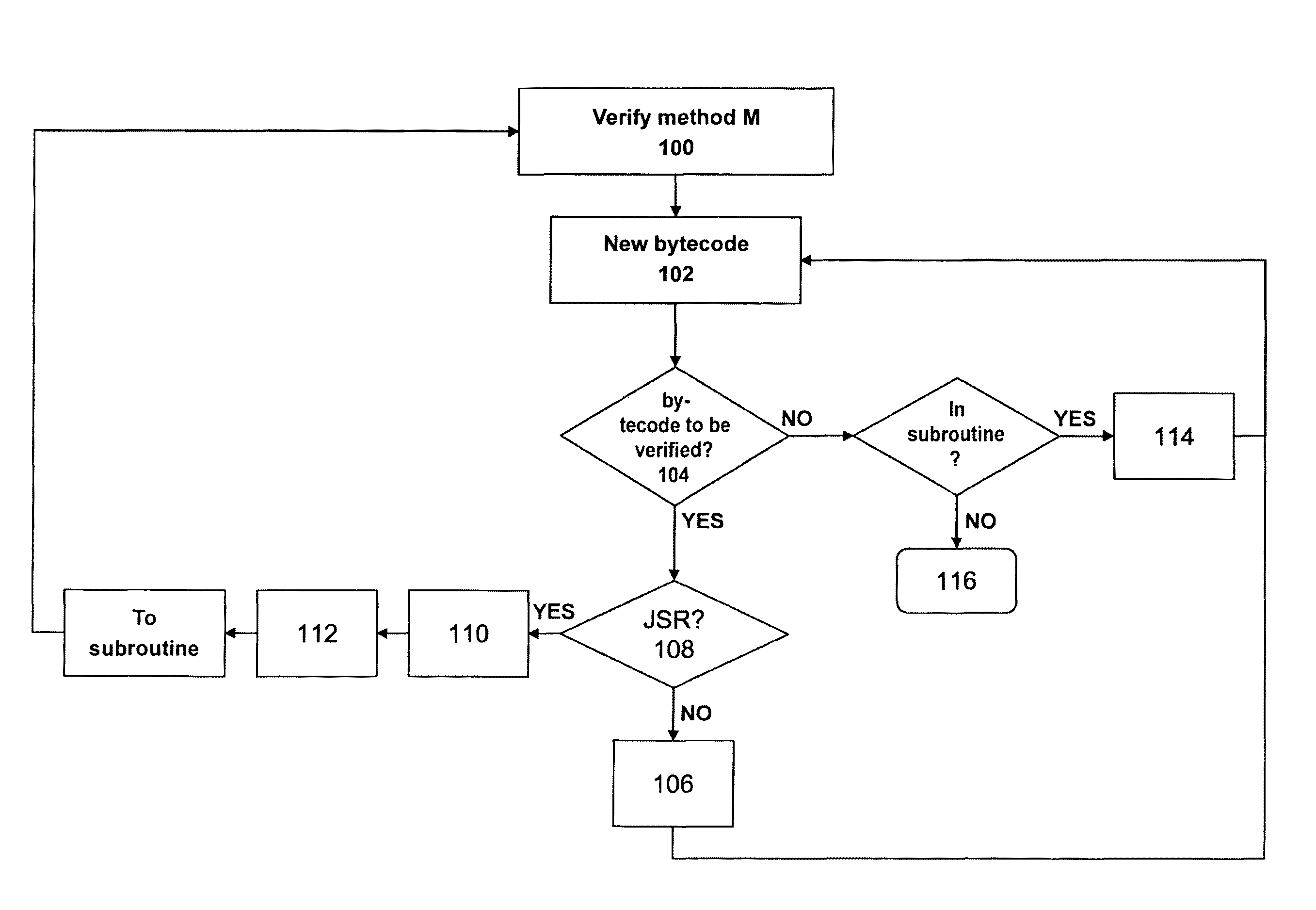
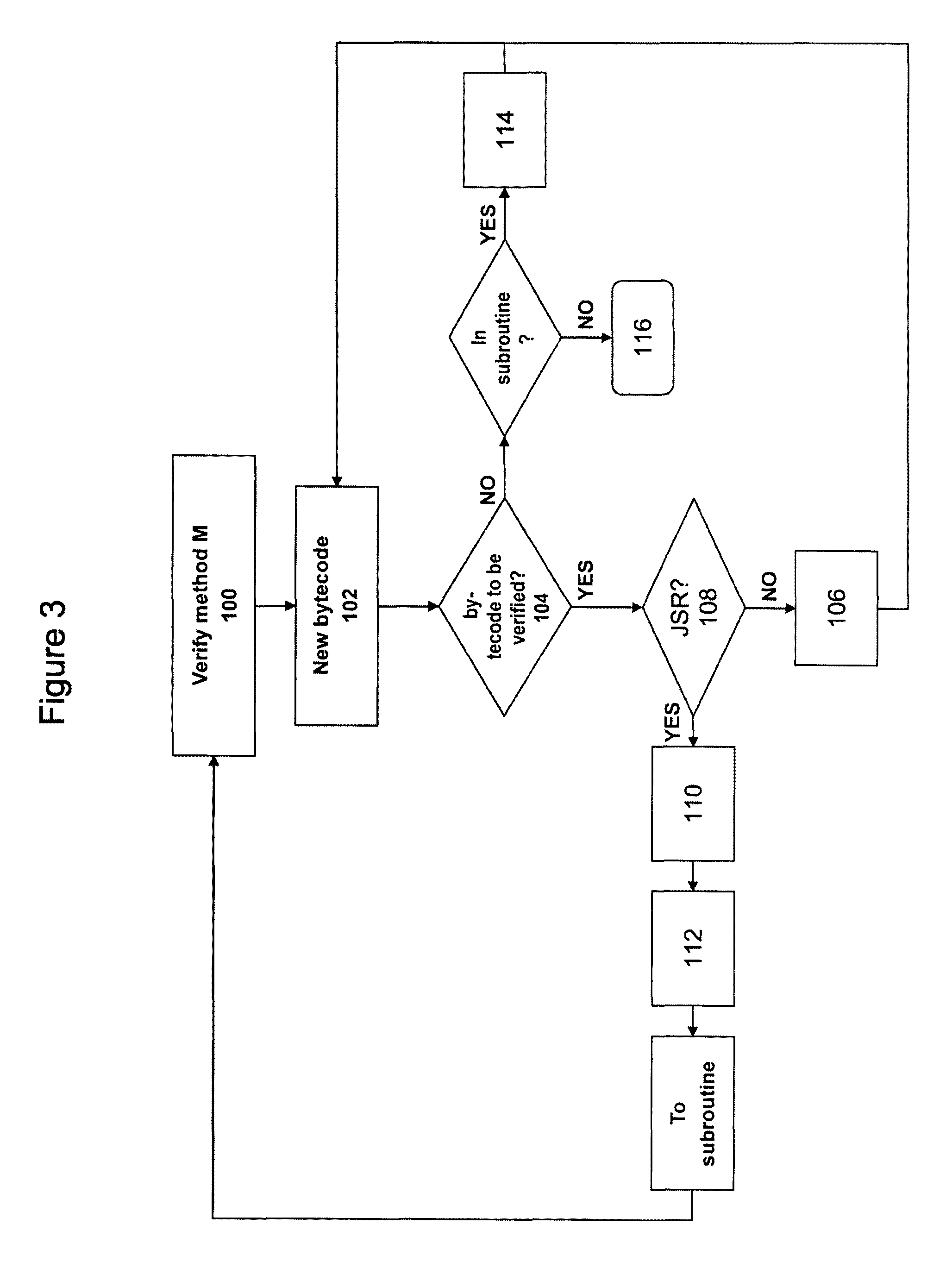
[0048]In the implementations given below by way of example, the Java (Registered Trademark) subroutines called by JSR instructions are merely one example of subprograms that can be called generally and to which the invention relates.

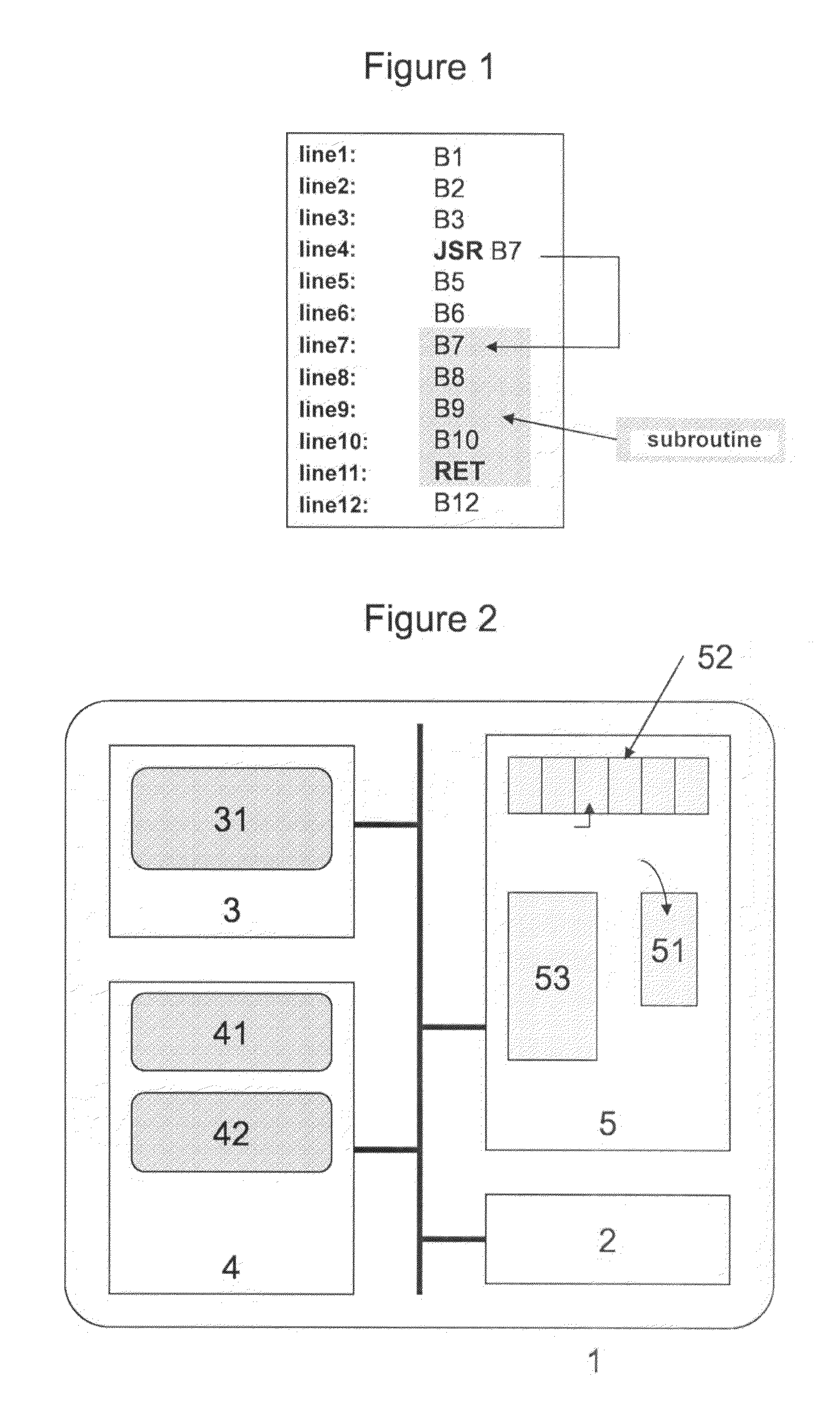
[0049]With reference to FIG. 2, the card module 1 comprises a microprocessor 2 controlling a non-volatile memory 3, e.g. of the flash type, a read-only memory (ROM) 4, and a random-access memory (RAM) 5.

[0050]The ROM 4 stores the bytecode verifier computer programs 41 and the virtual machine 42 making it possible to execute the bytecode. The term “virtual machine” is used to mean a machine which, during execution of bytecodes, manages a stack 51 and registers 52 in RAM 5. The stack 51 is a top-access memory in which data is stacked and from which data is unstacked. The registers 52 are memory registers having indexed access or free access: any information in the registers can be accessed.

[0051]A program or application 31 to be verified is stored in the f...


PUM


Abstract

The invention relates to a verification of applications in interpreted language of the byte-code type (pseudo-code) loaded on portable electronic devices, in particular a chipcard and a method for verification of an application (31) interpreted by a virtual machine (42), said application being loaded on a portable electronic device (1), comprising at least one processor (2) and one RAM (5). The method comprises carrying out the following after loading said application in the device and before validation thereof, checks in the code of said application by means of a process carried out by the processor (2), characterized in comprising, on starting a sub-program, a step of backing up the actual verification context (200 to 203) in the RAM (5), a step for creation and activation of a new verification context (206 to 209) for the sub-program and a step for restoration of the verification context (200 to 203) previously backed-up.

Description

BACKGROUND OF THE INVENTION[0001]The present invention relates to a method of verifying consistency of codes for an embedded system.[0002]The invention relates more particularly, but not exclusively, to the field of applications in interpreted language of the bytecode (pseudo-code) type that are loaded in a smart card.[0003]The term “embedded system” is used below in the broad sense, in particular to designate a system designed for any portable electronic device, e.g. a smart card (chip card) whose processing and storage resources are relatively limited.[0004]Similarly, an “interpreted language” is a non-compiled language in which execution of the lines of code requires the presence of auxiliary means making it possible to interpret the code. An example of such a language is the Java (Registered Trademark) language that is in very widespread use in application solutions for smart cards. The Java application or “applet” is interpreted by an associated Java Virtual Machine (JVM). Hard...

Claims


Application Information

Patent Timeline
Patent Type & Authority Patents(United States)
IPC IPC(8): G06F12/00
CPCG06F9/44589
Inventor BENOIT, ALEXANDREGAUTERON, LAURENT
Owner GEMPLU
Why Eureka
Try Eureka