Scribing method, cutter wheel, scribing device using the cutter wheel, and cutter wheel manufacturing device for manufacturing the cutter wheel
a manufacturing device and cutter wheel technology, applied in the direction of manufacturing tools, paper/cardboard containers, box making operations, etc., can solve the problems of no commercial value as a liquid crystal panel, defects (horizontal cracks) may be caused, and cracks may form
- Summary
- Abstract
- Description
- Claims
- Application Information
AI Technical Summary
Benefits of technology
Problems solved by technology
Method used
Image
Examples
example 1
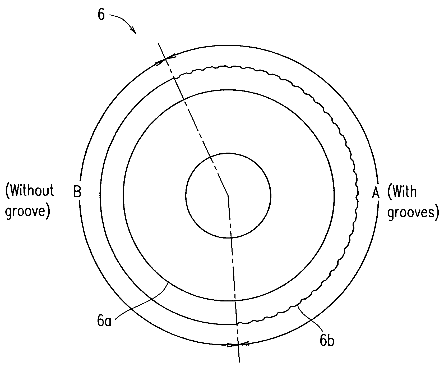
[0082]FIG. 10 shows an embodiment of a glass cutter wheel of Example 1. TABLE 2 below shows dimensions of the glass cutter wheel of Example 1, such as a wheel diameter or the like.
[0083]
TABLE 2Wheel diameter φ 2.0 mmWheel thickness w0.65 mmBlade edge angle α 135°Depth of groove 7 μm
[0084]The glass cutter wheel 6 of Example 1 was designed such that grooves having identical depths (7 μm) are continuously formed over a 1 / 10 portion (8 divisions / 80 divisions) of the entire perimeter length of the edge line portion.
[0085]This glass cutter wheel 6 was used to scribe an alkali-free glass plate having a thickness of 0.7 mm with a blade edge load of 0.16 to 0.40 MPa and at a scribing speed of 400 mm / s. In the scribing process using the glass cutter wheel 6 of Example 1, a scribe line where the depth of a vertical crack periodically varies was formed as shown in FIG. 7. In the case where a load of 0.18 MPa was used, the deep vertical crack DA shown in FIG. 7 was about 400 μm, and the shallow...
example 2
[0086]FIG. 11 shows an embodiment of a glass cutter wheel 6 of Example 2. TABLE 3 below shows dimensions of the glass cutter wheel shown in FIG. 11, such as a wheel diameter or the like.
[0087]
TABLE 3Wheel diameter φ 2.0 mmWheel thickness w0.65 mmBlade edge angle α 135°Depth of groove 7 μm
[0088]The glass cutter wheel 6 of Example 2 has regions A1 and A2 at two separated positions in the perimeter of the glass cutter wheel 6, each of which is a 1 / 10 portion (8 divisions / 80 divisions) of the entire perimeter length of the edge line portion, where grooves having identical depths (7 μm) are continuously formed. Regions A1 and A2, where grooves are formed, are provided at opposite sides of the glass cutter wheel 6 with respect to the central axis of the glass cutter wheel 6.
[0089]This glass cutter wheel 6 was used to scribe an alkali-free glass plate having a thickness of 0.7 mm with a blade edge load of 0.16 to 0.40 MPa and at a scribing speed of 400 mm / s. In the scribing process using ...
example 3
[0090]FIG. 12 shows an embodiment of a glass cutter wheel 6 of Example 3. TABLE 4 below shows dimensions of the glass cutter wheel 6 of Example 3, such as a wheel diameter or the like.
[0091]
TABLE 4Wheel diameter φ 2.0 mmWheel thickness w0.65 mmBlade edge angle α 135°Depth of groove 7 μm
[0092]The glass cutter wheel 6 of Example 3 has regions A1, A2, and A3 at three separated positions in the perimeter of the glass cutter wheel 6, each of which is a 1 / 10 portion (8 divisions / 80 divisions) of the entire perimeter length of the edge line portion, where grooves having identical depths (7 μm) are continuously formed. Regions A1, A2, and A3 are provided at uniform intervals.
[0093]This glass cutter wheel 6 was used to scribe an alkali-free glass plate having a thickness of 0.7 mm with a blade edge load of 0.16 to 0.40 MPa and at a scribing speed of 400 mm / s. In the scribing process using the glass cutter wheel 6 of Example 3, a scribe line where the depth of a vertical crack periodically v...
PUM
| Property | Measurement | Unit |
|---|---|---|
| Diameter | aaaaa | aaaaa |
| Diameter | aaaaa | aaaaa |
| Diameter | aaaaa | aaaaa |
Abstract
Description
Claims
Application Information
 - R&D
- Intellectual Property
- Life Sciences
- Materials
- Tech Scout
- Unparalleled Data Quality
- Higher Quality Content
- 60% Fewer Hallucinations
Browse by: Latest US Patents, China's latest patents, Technical Efficacy Thesaurus, Application Domain, Technology Topic, Popular Technical Reports.
© 2025 PatSnap. All rights reserved.Legal|Privacy policy|Modern Slavery Act Transparency Statement|Sitemap|About US| Contact US: help@patsnap.com


