
Effect system

a technology of effect system and effect, which is applied in the direction of measurement device, speed/acceleration/shock measurement, instruments, etc., can solve the problems of difficult parallel connection of such devices, difficult to achieve certain desired effects with serial connections of such prior devices, and relatively complex configuration of such a system

Active Publication Date: 2009-04-28
ROLAND CORP
View PDF13 Cites 12 Cited by
  • Summary
  • Abstract
  • Description
  • Claims
  • Application Information

AI Technical Summary

Benefits of technology

The present invention relates to an effect device that can easily connect with other effect devices in parallel. The device has an input terminal for musical sound signals, an effect add means for adding effects on the signals, an output terminal for outputting the signals, a send terminal for adding the signals to a return terminal, and a mixing means for mixing the signals. The device can select between the signals from the input terminal or the effect add means and the signals from the return terminal or the effect device in series or parallel modes. The device can also have an internal effect switching means for selecting the effect add means or an external effect switching means for selecting between the effects from the effect add means and the effects from the other connected effect devices. The device can also have a phase reversal means and a reversal switching means to prevent discomforting color of sound when the phase of the signals is reversed. The device can also have a pedal switch for easy operation with the player's foot.

Problems solved by technology

However, there can be difficulties in trying to achieve a parallel connection of such devices where musical sound signals are input to multiple effect devices and the output of the effect devices are mixed without one effect device becoming dominant over the other(s).
The configuration of such a system has been known to be relatively complex.
For this reason it can be impossible to have certain desired effects with the serial connections of such prior devices.

Method used


Image

  • Effect system
  • Effect system
  • Effect system

Examples


first embodiment

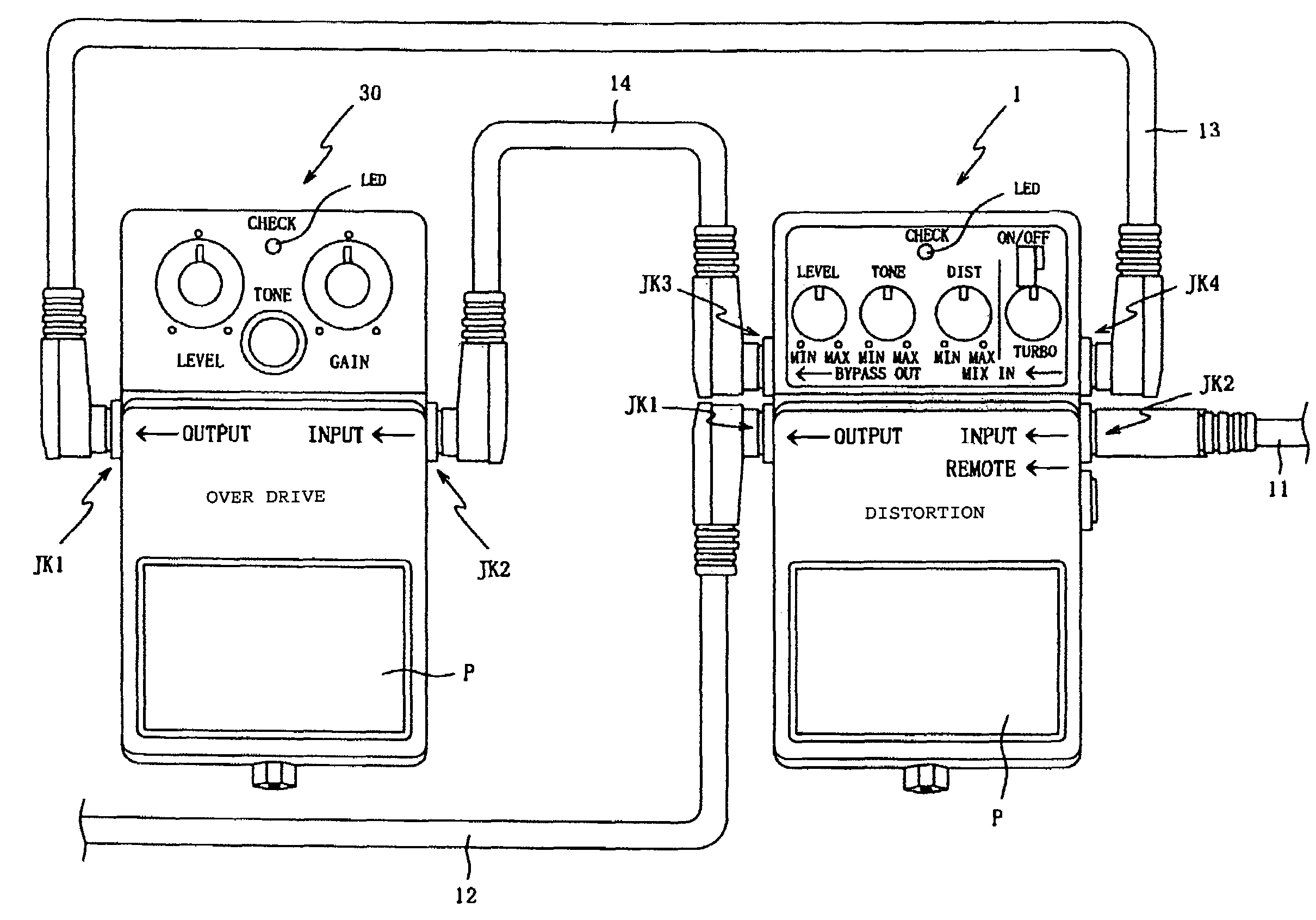
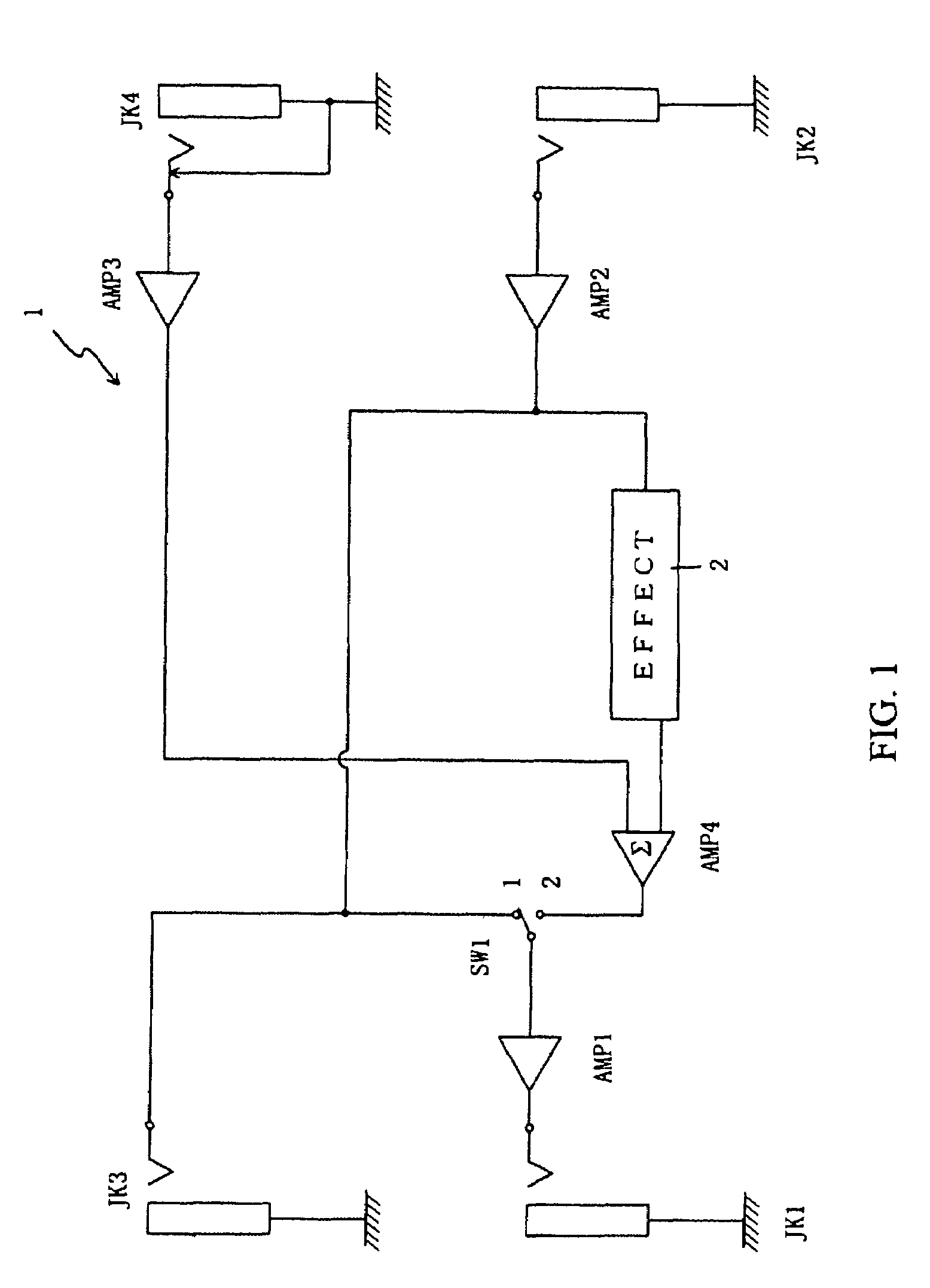
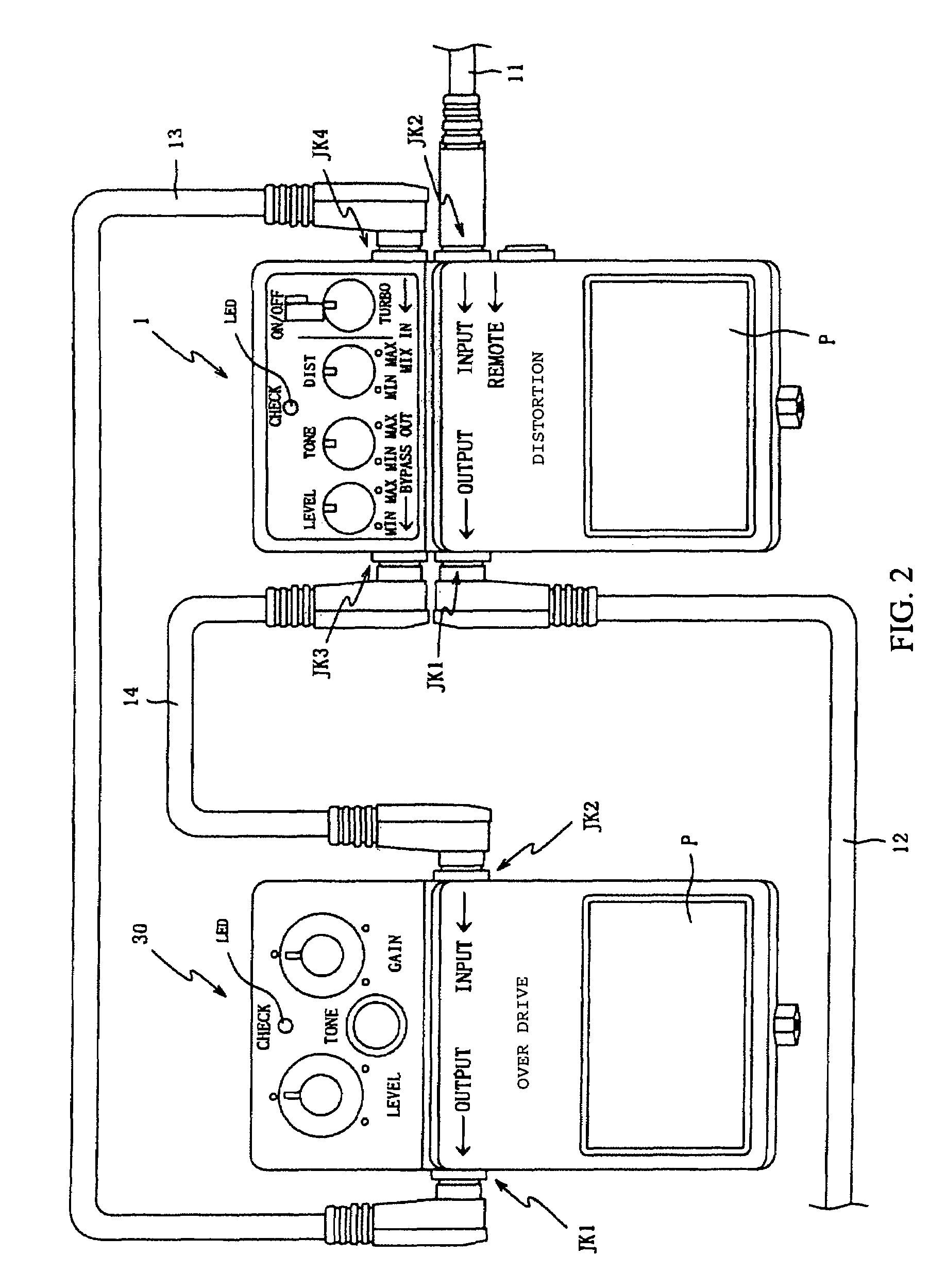
[0036]FIG. 1 is a block diagram that depicts the electrical configuration of an effect device 1 based on the invention. The effect device 1 includes: Input Jack JK 2; Amplifier AMP 1; Amplifier AMP 2; Amplifier AMP 3; Amplifier AMP 4; Switch SW 1; Effect Add Circuit 2; Output Jack JK 1; Send Jack JK 3; and Return Jack JK 4.

[0037]Input Jack JK 2 may comprise a traditional device that receives a plug on one end of a connecting cord that connects with an electric guitar, synthesizer, or other suitable instruments, so that the musical sound signals from the electric guitar; synthesizer, or other suitable instruments will be inputted.

[0038]Amplifier AMP 1, Amplifier AMP 2, and Amplifier AMP 3 may be buffers. Amplifier AMP 4 mixes the musical sound signals that are input from two inputs, and outputs them. Effect Add Circuit 2, may be configured, for example like traditional devices, to give input musical sound signals such effects as distortion or delay.

[0039]The musical sound signals tha...

third embodiment

[0054]As shown in FIG. 4, Effect Device 1 of the third embodiment is equipped with Switch SW 3 that can switch three circuits (Circuit A, B, and C) all at the same time. Circuit A selects the musical sound signals that are input from Return Jack JK 4 and output from Amplifier AMP 3, to connect to either the input of Amplifier AMP 4 (1 Side) or to the Terminal 2 of Circuit C which then switches the connection with the Output Jack JK 1 (2 Side).

[0055]Circuit B selects the output of Jack JK 3 to be either the musical sound signals that were the input of the Input Jack JK 2 and the output of the Amplifier AMP 2 (1 Side), or the musical sound signals that were output to Amplifier AMP 1 (2 Side). Circuit C switches the connection for Output Jack JK 1, and selects either the musical sound signals that were output from the Amplifier AMP 1 (1 Side), or the musical sound signals that are inputted from Return Jack JK 4 which are connected with Terminal 2 of Circuit A and are outputted from Amp...

fourth embodiment

[0067]FIG. 5 refers to a block diagram that shows an electrical configuration of an Effect Device 1 based on a Again for those sections that are identical with the Effect Device 1 of the previously presented embodiments, the descriptions are omitted and same marks are used. Only the sections that are different from the previous embodiments are described.

[0068]In a third embodiment, Switch SW 4 enables the device bypass the internal Effect Add Circuit 2 so that only the externally-connected Effect Device 30 adds effect under a series mode and then directly outputs the musical sound signals that were input on Input Jack JK 2 under parallel mode.

[0069]In this fourth embodiment, when the internal Effect Add Circuit 2 does not add effect with switching Switch SW 4, the device can have only the externally-connected Effect Device 30 add effect, regardless of the series mode or the parallel mode.

[0070]In this embodiment, the device is equipped with Switch SW 4 which switches two circuits (...


PUM


Abstract

The disclosure presented here involves an effect device that can easily connect with other effect devices in parallel. A preferred embodiment of this device is equipped with a number of components including an effect add means that adds effects, a mixing means that mixes the musical signals, a mode switching means that configures the operation from parallel mode to serial mode, and a phase reversal means that reverses the phase of the musical sound signals. Various combinations using the above means are possible and are presented in this disclosure. The output terminal outputs the musical sound signals that were selected, mixed, and or treated by the enabled features of the underlying embodiments.

Description

CROSS-REFERENCE TO RELATED PATENT APPLICATIONS[0001]The present invention relates to Japan patent application number 2006-129396, filed on May 8, 2006, which is incorporated herein by reference in its entirety.BACKGROUND OF THE INVENTION[0002]1. Field of the Invention[0003]The present invention generally relates to the field of effect devices that can connect with other effect devices in parallel.[0004]2. Related Art[0005]Various types of effect devices (effectors) that add effects to input musical sound signals and then output the resulting sounds, have been known. Such effect devices include compact effectors which add different effects for the output of electric guitars equipped with pedal switch, or the multiple effector which can use a combination of multiple effects.[0006]FIG. (Diagram) 7 is a block diagram that depicts an electrical configuration of a traditional Effect Device 30. This device has an input Jack JK 2; two amplifiers, AMP 1 and AMP 2; one Switch SW 1; an effect ...

Claims


Application Information

Patent Timeline
Patent Type & Authority Patents(United States)
IPC IPC(8): G01P3/00G10H1/02
CPCG10H1/0091G10H1/348G10H2210/311
Inventor YAMADA, YASUYUKI
Owner ROLAND CORP
Learn More