Lamb wave type high frequency device

a high frequency device and a technology of a beam wave are applied in the direction of impedence networks, electrical devices, etc., which can solve the problems of increasing loss of electric resistance, further phase velocity decrease, and inability to achieve desired resonance characteristics, etc., to achieve high frequency, suppress spurious, and achieve high frequency.

Inactive Publication Date: 2009-05-05
SEIKO EPSON CORP
View PDF25 Cites 17 Cited by
  • Summary
  • Abstract
  • Description
  • Claims
  • Application Information

AI Technical Summary

Benefits of technology

[0028]An advantage of the invention is to provide a lamb wave type high frequency resonator in which the excitation of a mode to be used is intensified and a spurious is suppressed.
[0029]According to a first aspect of the invention, a lamb wave type high frequency device includes: an IDT electrode in which an electrode finger is interdigitated; a pair of reflectors that have an electrode finger and disposed at both sides of a propagation direction of a lamb wave excited by the IDT electrode; and a piezoelectric substrate on a surface of which the IDT electrode and the reflectors are disposed. A pitch of the electrode finger of the IDT electrode and a pitch of the electrode finger of the reflectors are different from one another.
[0030]According to the structure, high frequency can easily be achieved since the lamb wave can be excited. Since the pitch of the electrode finger is different, which is conventionally the same, in the reflectors and the IDT electrode, the mode to be selectively used can be intensively excited, and simultaneously the spurious can be suppressed.
[0031]It is preferable that two electrode fingers adjacent each other in the IDT electrode are interdigitated in the range of the wavelength λ of a lamb wave.
[0032]According to the structure, there is an effect in that the lamb wave type high frequency device can be downsized by reducing the number of electrode fingers included in reflectors since the spurious can effectively be suppressed by reflector design and a reflection wave produced by the IDT electrode can be utilized.
[0033]It is preferable that two sets of electrode fingers, one set of which is composed of two electrode fingers adjacent each other, among electrode fingers of the IDT electrode are interdigitated in the range of the wavelength λ of a lamb wave.

Problems solved by technology

However, it causes a disadvantage in that loss in electric resistance increases and further the phase velocity decreases.
However, the element has a disadvantage in that a desired resonance characteristic is not achieved due to so-called a spurious, in which another oscillation mode arises during the excitation of a selected oscillation mode since the exciting strength of an oscillation mode to be selectively used is low.
This possibly results in other modes being exhibited as a spurious since they are not suppressed if the frequency of mode E is used for an oscillator, easily causing failures such as abnormal oscillations or frequency jumps.
In addition, if it is employed to filter applications, there arises a problem of ripples in frequency bands.

Method used


Image

  • Lamb wave type high frequency device
  • Lamb wave type high frequency device
  • Lamb wave type high frequency device

Examples


first embodiment

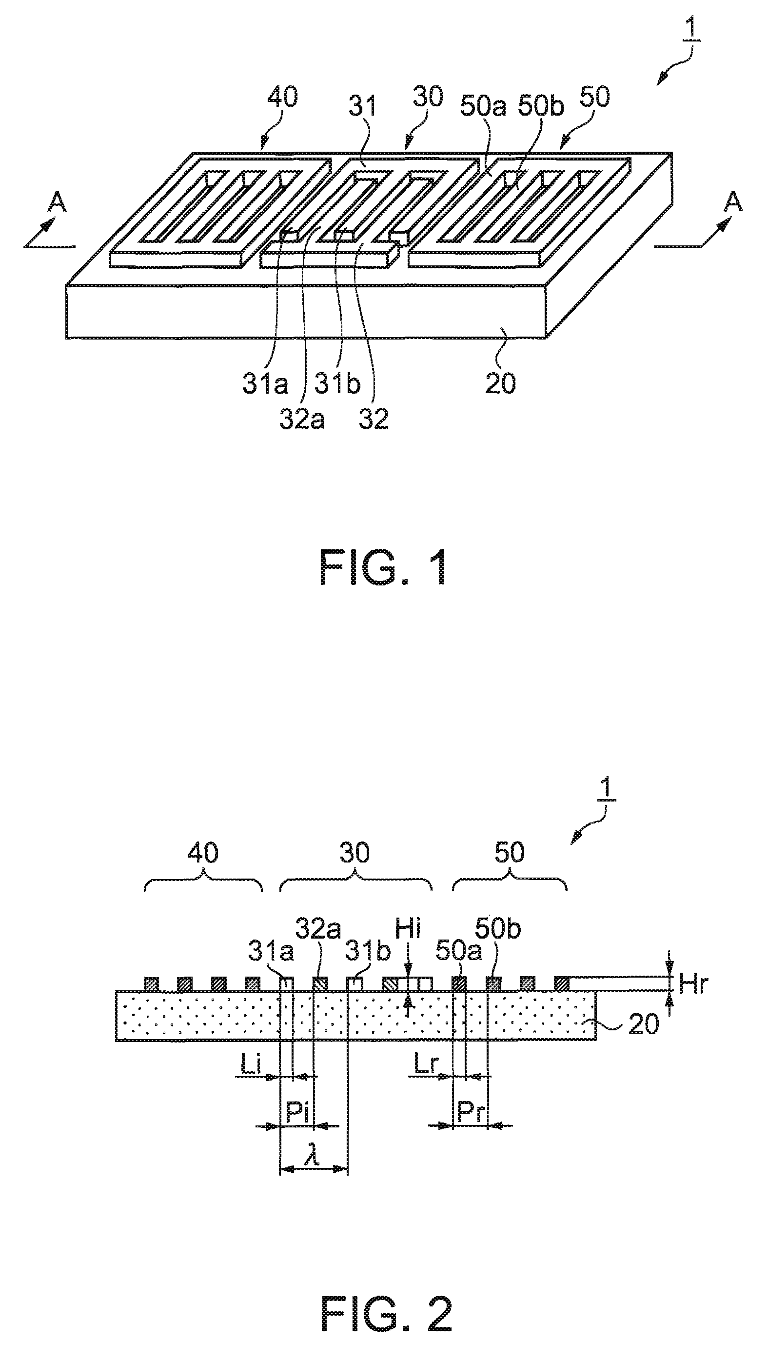
[0152]FIG. 1 is a perspective view illustrating a lamb wave type high frequency resonator 1 according to a first embodiment. FIG. 2 is a cross-sectional view taken along the line A-A in FIG. 1.

[0153]In FIGS. 1 and 2, the lamb wave type high frequency resonator 1 is composed of an IDT electrode 30 including a pair of interdigital finger electrodes 31 and 32, a pair of reflectors 40 and 50 including electrode fingers 50a and 50b, and a piezoelectric substrate 20 made of quartz crystal. The IDT electrode 30, and the reflectors 40 and 50 are fabricated on the surface of the piezoelectric substrate 20. The reflectors 40 and 50 are disposed at both sides of the propagation direction of a lamb wave excited by the IDT electrode 30. Hereinafter, an interdigital finger electrode 31 at one side is called as a first interdigital finger electrode 31, while an interdigital finger electrode 32 at the other side is called as a second interdigital finger electrode 32.

[0154]In the IDT electrode 30, t...

second embodiment

[0166]Next, a lamb wave type high frequency resonator according to a second embodiment of the invention will be described with reference to accompanying drawings. As compared with the first embodiment (refer to FIGS. 1 and 2), the second embodiment differs in the stricture of the electrode finger of the IDT electrode, and is featured in that four electrode fingers of the IDT electrode are interdigitated in the range of the wavelength λ of the lamb wave.

[0167]FIGS. 6 and 7 show the structure of the lamb wave type high frequency resonator of the second embodiment. FIG. 6 is a perspective view. FIG. 7 is a cross-sectional view taken along the line B-B in FIG. 6. In FIGS. 6 and 7, a lamb wave type high frequency resonator 2 is composed of the IDT electrode 30, the reflectors 40 and 50 disposed at both sides of the IDT electrode 30, and the piezoelectric substrate 20 made of quartz crystal. The IDT electrode 30 and the reflectors 40 and 50 are fabricated on the surface of the piezoelectr...

third embodiment

[0177]Next, a lamb wave type high frequency resonator according to a third embodiment of the invention will be described with reference to accompanying drawings. The third embodiment is featured in that insulation film is formed so as to cover the upper surface of the IDT electrode 30 described in the first and second embodiments. The IDT electrode 30 and the reflectors 40 and 50 can be structured as the same as those in the first and second embodiments. Here, the structure based on the first embodiment (refer to FIGS. 1 and 2) is exemplified. Common parts are given the same numerals and only different parts will be described.

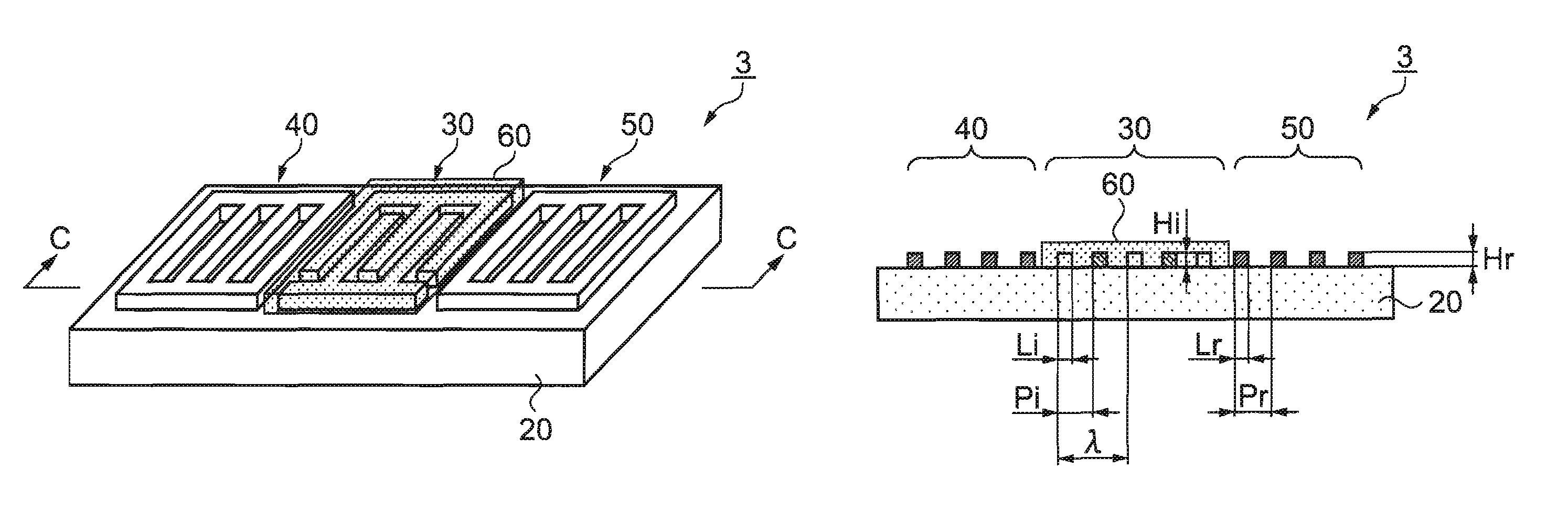
[0178]FIGS. 9 and 10 show a lamb wave type high frequency resonator 3 of the third embodiment. FIG. 9 is a perspective view. FIG. 10 is a cross-sectional view taken along the line C-C in FIG. 9. In FIGS. 9 and 10, an insulation film 60 is deposited on the surface of the IDT electrode 30 so as to cover the whole IDT electrode 30. The insulation film 60 is made o...


PUM


Abstract

A lamb wave type high frequency device includes: an interdigital transducer (IDT) electrode having an electrode finger interdigitated therein; a pair of reflectors having an electrode finger and being disposed at both sides of a propagation direction of a lamb wave excited by the IDT electrode; and a piezoelectric substrate on a surface of which the IDT electrode and the reflectors are disposed, wherein a pitch of the electrode finger of the IDT electrode and a pitch of the electrode finger of the reflectors are different from one another.

Description

BACKGROUND[0001]1. Technical Field[0002]The present invention relates to a lamb type wave high frequency device used for communication apparatuses.[0003]2. Related Art[0004]High frequency devices are well known as devices included in high frequency resonators or filters. Typical examples of the high frequency resonator include surface acoustic wave elements using Rayleigh wave or an SH wave, and lamb wave elements using a lamb wave, which is a bulk wave. Some bandwidth filters also use the same waves as described above.[0005]For example, a Rayleigh wave type surface acoustic wave element is known in which an interdigital transducer (IDT) electrode is formed in the Z′ axis direction, in which a surface acoustic wave is propagated, on the surface of a quartz crystal substrate called as an ST cut. The element is, for example, cited in a first example of related art.[0006]A surface acoustic wave element using an STW cut quartz crystal substrate is also known, i.e. an SH wave type surfac...

Claims


Application Information

Patent Timeline
Patent Type & Authority Patents(United States)
IPC IPC(8): H03H9/00H03H9/25H03H9/125
CPCH03H9/02551H03H9/02842H03H9/14552H03H9/6426H03H9/643H03H9/02228H03H9/25H03H9/145
Inventor TANAKA, SATORU
Owner SEIKO EPSON CORP
Why Eureka
Try Eureka