Integrated cavity filter

A cavity filter and main cavity technology, applied in waveguide devices, electrical components, circuits, etc.

Active Publication Date: 2014-02-19
CHINA ELECTRONIC TECH GRP CORP NO 38 RES INST
View PDF7 Cites 4 Cited by
  • Summary
  • Abstract
  • Description
  • Claims
  • Application Information

AI Technical Summary

Problems solved by technology

[0003] In order to meet both the reliability requirements of the airborne radar system and the requirements of high power capacity, the fundamental wave signal of the radar auxiliary antenna to the radar main antenna is finally solved The interference problem of the digital array module, and the second harmonic and the fourth harmonic problem output by the digital array module in the main antenna should be suppressed, and the performance index of the whole machine will not be affected after being connected to the main radar system. The present invention provides an integrated cavity filter

Method used


Image

  • Integrated cavity filter
  • Integrated cavity filter
  • Integrated cavity filter

Examples


Embodiment 1

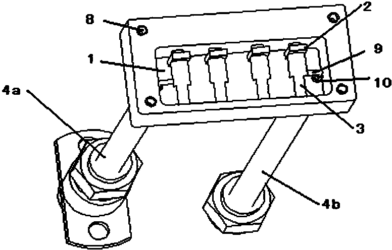
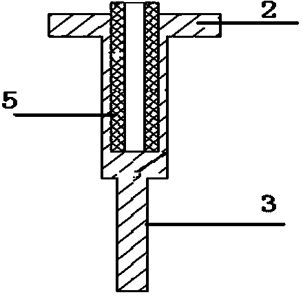
[0026] The invention is mainly used in a phased array radar receiving system. On the basis of ensuring the electrical performance of the microwave filter, a coaxial resonator 3 with multi-section impedance transformation is adopted, and a square metal resonator is added at the open end of the coaxial resonator. Block 2 and dielectric ring 5, open-circuit terminal plus adjustable loading capacitance, make the resonator resonate at the required frequency, and the physical length of the resonator is about 1 / 3 shorter than that of similar resonators. The design size of the microwave filter and the coupling size of the critical resonator are determined by the bandwidth of the required filter. In this embodiment, the required bandwidth of the filter is 9.2%. By analyzing the design index of the filter, it is determined by Chebyshev When n=4, the general prototype filter can meet the index requirements proposed by the system. By adopting the design method and engineering design optimi...

Embodiment 2

[0029]The integrated filter components of the present invention adopt a coaxial cavity filter with a high Q value and a cable with a blind-mating joint in the system for an integrated design, and optimize the design under the volume and size required by the system to achieve a small volume, Small loss, good passband characteristics and stopband characteristics at the same time, can be widely used in radar systems with fast blind insertion structures in various frequency bands, modern mobile communication systems, and 3G mobile phone communication systems. Microwave filters are key components in microwave communication or radar systems, and have good economic and practical values.


PUM


Abstract

The invention relates to an integrated cavity filter which comprises a metal main cavity in the shape of a flat box. Coaxial resonators are arranged in the metal main cavity. Tubular medium rings are arranged in blind holes of open circuit ends of the coaxial resonators. Tuning bolts are penetrated into the medium rings of the open circuit ends of the coaxial resonators through threaded holes in the metal main cavity. An input cable and an output cable are arranged at the bottom of the metal main cavity respectively. The integrated cavity filter is convenient to use and additionally arranged into a main radar system and an original telecommunication interface manner does not need to be changed. The size of the coaxial resonators in the filter is far smaller than . On the other hand, compared with the conventional filter, the power-resistant capability of the filter is improved by seven times to eight times. Restrained bandwidth with the frequency band which is four times larger than the original frequency band is achieved, the electromagnetic interference problem of the radar system can be well solved and straying can be well hindered.

Description

technical field [0001] The invention belongs to the technical fields of radar, microwave communication, satellite communication system, etc., and specifically relates to a microwave cavity loaded with capacitance and highly integrated with SMA and SBMA (SMA blind mating) low standing wave, low loss and high phase stability cable assemblies bulk filter. Background technique [0002] In a radar system, due to the integrated design of the main radar antenna and the auxiliary radar antenna (with different frequency bands), the mutual coupling between them is too strong, and the auxiliary radar antenna causes strong electromagnetic interference to the main antenna. In order to meet the requirements of the radar system, it is necessary to install an integrated filter with small size, special assembly interface, low loss, high suppression of auxiliary radar frequency points, and wide stop band on the main antenna. Hybrid (low-pass, band-pass, high-pass), plate-line interdigitated,...

Claims


Application Information

Patent Timeline
Patent Type & Authority Applications(China)
IPC IPC(8): H01P1/205
Inventor 汤艳燕李佩张德智王志勇
Owner CHINA ELECTRONIC TECH GRP CORP NO 38 RES INST
Why Eureka
Try Eureka