Acoustic wave device and module including a dielectric film with an inclined upper surface

a dielectric film and acoustic wave technology, applied in piezoelectric/electrostrictive/magnetostrictive devices, piezoelectric/electrostriction/magnetostriction machines, electrical apparatus, etc., can solve the problem of insufficient suppression of spurious, difficult to scatter acoustic wave within the dielectric film, and reduce reliability.

Active Publication Date: 2014-11-25
TAIYO YUDEN KK
View PDF14 Cites 4 Cited by
  • Summary
  • Abstract
  • Description
  • Claims
  • Application Information

AI Technical Summary

Benefits of technology

[0006]According to an aspect of the present invention, there is provided an acoustic wave device including: a substrate; a dielectric film formed on the substrate; opposing comb-shaped electrodes located between the substrate and the dielectric film, each of the opposing comb-shaped electrodes including an electrode finger, wherein at least one of the substrate and the dielectric film is a piezoelectric substance; an upper surface of the dielectric film, which is located above a gap between a tip of an electrode finger of one of the opposing comb-shaped electrodes and the other of the opposing comb-shaped electrodes, is inclined against an upper surface of the substrate in an extension direction of the electrode finger, and an inclination angle of the upper surface of the dielectric film against the upper surface of the substrate is equal to or larger than 30° and equal to or smaller than 50°. According to the present invention, it is possible to suppress a spurious.

Problems solved by technology

However, generated is a lateral-mode spurious caused by the acoustic wave propagated to a direction of the electrode fingers.
However, it is difficult to scatter the acoustic wave within the dielectric film.
Therefore, the suppression of the spurious is not sufficient.
This may decrease a reliability.

Method used


Image

  • Acoustic wave device and module including a dielectric film with an inclined upper surface
  • Acoustic wave device and module including a dielectric film with an inclined upper surface
  • Acoustic wave device and module including a dielectric film with an inclined upper surface

Examples


first embodiment

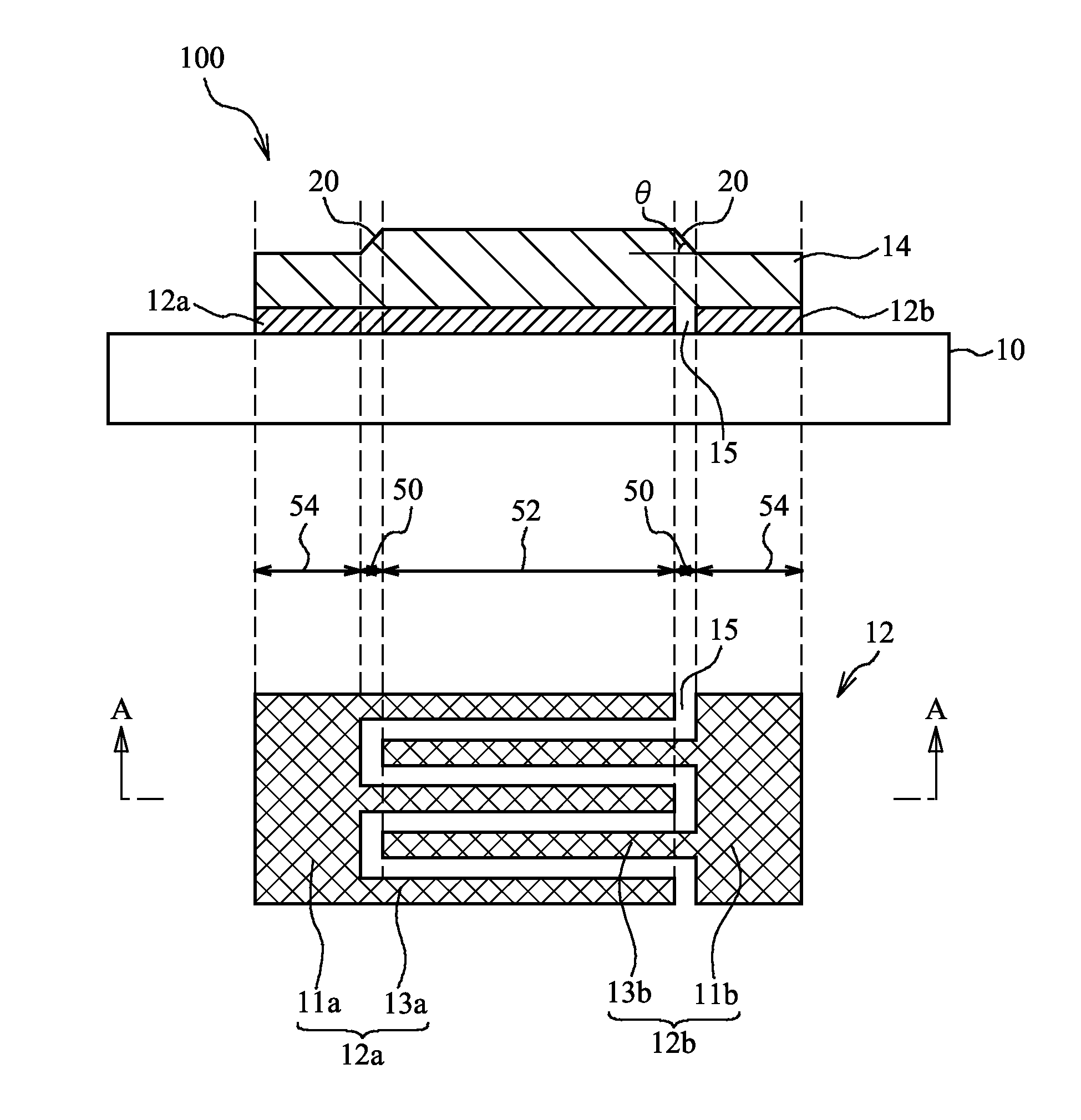
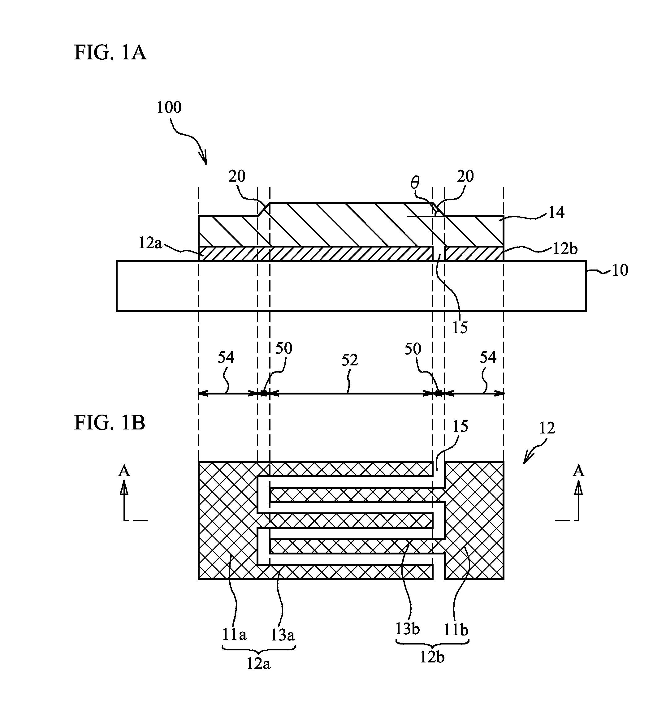
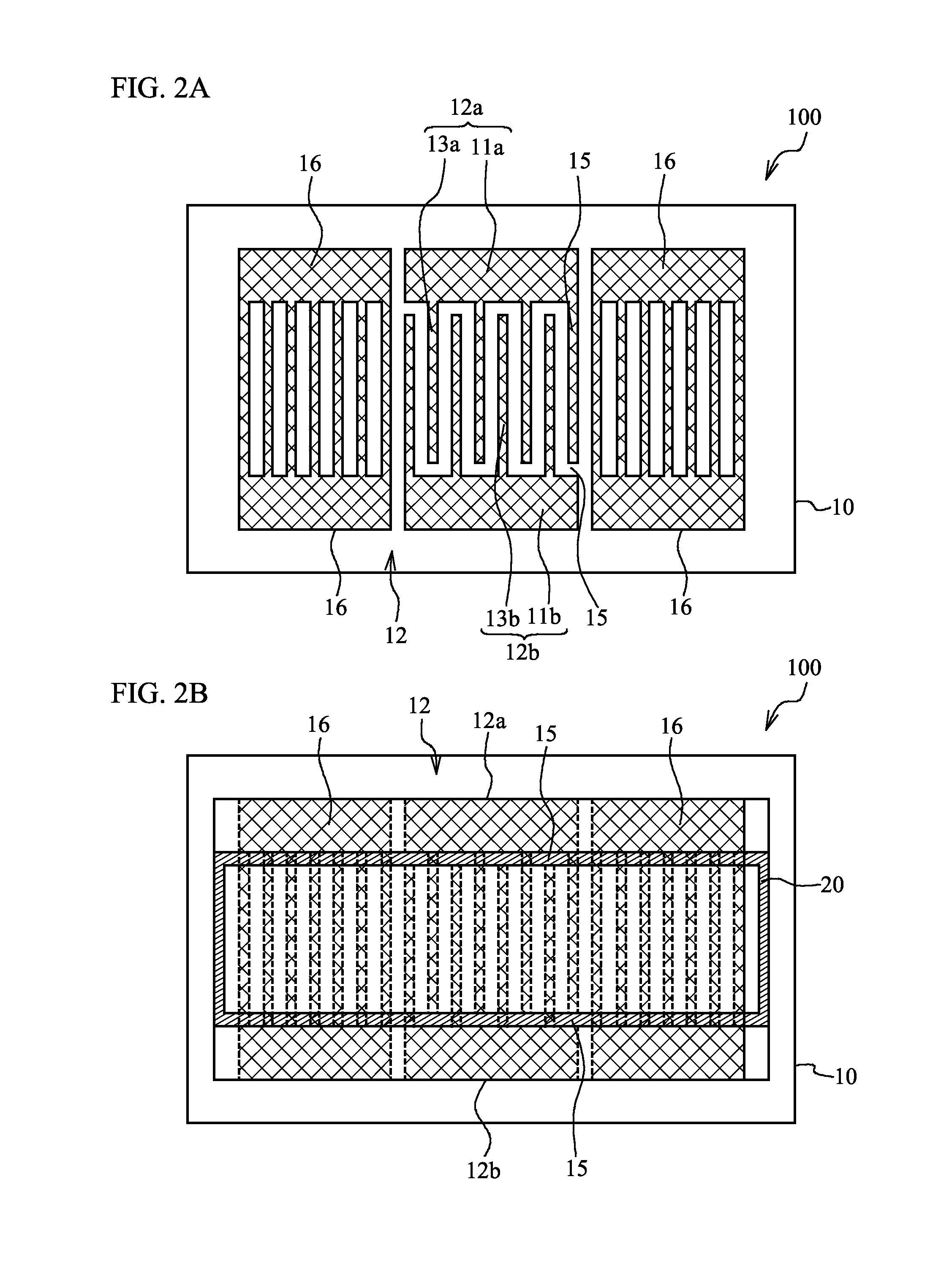
[0030]A first embodiment is an exemplary resonator as an acoustic wave device. FIG. 1A is a cross-sectional view of a resonator 100 in accordance with the first embodiment, and FIG. 1B is a plain view of a part of the resonator 100. FIG. 1A corresponds to a cross-sectional view taken along line A-A in FIG. 1B. As illustrated in FIG. 1A and FIG. 1B, a dielectric film 14 such as a silicon oxide film is formed on a substrate 10 having a piezoelectricity such as lithium niobium oxide or lithium tantalum oxide for example. Comb-shaped electrodes 12a and 12b made of a metal film such as Cu are formed between the substrate 10 and the dielectric film 14. The comb-shaped electrodes 12a and 12b are formed so as to oppose each other, and form an IDT 12. The comb-shaped electrodes 12a and 12b have electrode fingers 13a and 13b and bus bars 11a and 11b respectively. The electrode fingers 13a and 13b extend to a same direction, and the electrode fingers 13a and 13b are arranged alternately. A reg...

second embodiment

[0056]The second embodiment is an exemplary filter as the acoustic wave device. FIG. 18 is a circuit diagram of a ladder-type filter 115 in accordance with the second embodiment. As illustrated in FIG. 18, series resonators S1 through S3 are connected in series between an input terminal Tin and an output terminal Tout. Parallel resonator P1 and P2 are connected in parallel between the input terminal Tin and the output terminal Tout. One ends of the parallel resonator P1 and P2 are connected to a ground Gnd.

[0057]FIG. 19 is a plain view of the ladder-type filter 115 in accordance with the second embodiment. The series resonators S1 through S3 and the parallel resonators P1 and P2 are formed on the substrate 10 having a piezoelectricity. The series resonators S1 through S3 and the parallel resonators P1 and P2 are the resonator in accordance with the first embodiment or the variations of the first embodiment. The resonators are electrically interconnected via wirings 22. Each resonato...

third embodiment

[0063]A third embodiment is an exemplary RF (Radio Frequency) module. FIG. 21 is a block diagram of a module 70 in accordance with the third embodiment. As illustrated in FIG. 21, the module 70 mainly includes a duplexer 73, a power amplifier 74, a transmission filter 75, a low noise amplifier 76 and a reception filter 77. The duplexer 73 has filters 71 and 72. A transmission signal is input to the transmission terminal Ttx. The transmission filter 75 filters the transmission signal. The power amplifier 74 amplifies the transmission signal. The filter 71 of the duplexer 73 filters the transmission signal, and outputs the transmission signal to the antenna terminal Tant. The filter 72 of the duplexer 73 suppresses the leakage of the transmission signal to the low noise amplifier 76 side. A reception signal is input to the antenna terminal Tant. The filter 72 of the duplexer 73 outputs the reception signal to the low noise amplifier 76. The filter 71 of the duplexer 73 suppresses the ...


PUM


Abstract

An acoustic wave device includes: a substrate; a dielectric film formed on the substrate; opposing comb-shaped electrodes located between the substrate and the dielectric film, each of the opposing comb-shaped electrodes including an electrode finger, wherein at least one of the substrate and the dielectric film is a piezoelectric substance, an upper surface of the dielectric film, which is located above a gap between a tip of an electrode finger of one of the opposing comb-shaped electrodes and the other of the opposing comb-shaped electrodes, is inclined against an upper surface of the substrate in an extension direction of the electrode finger, and an inclination angle of the upper surface of the dielectric film against the upper surface of the substrate is equal to or larger than 30° and equal to or smaller than 50°.

Description

CROSS-REFERENCE TO RELATED APPLICATION[0001]This application is a continuation application of PCT / JP2011 / 061471 filed May 19, 2011, the contents of which are herein wholly incorporated by reference.FIELD[0002]The present invention relates to an acoustic wave device and a module, and relates to an acoustic wave device and a module having a comb-shaped electrode for example.BACKGROUND[0003]Acoustic wave devices are used as filter elements and oscillators of wireless devices for example. There has been known a surface acoustic wave (SAW: Surface Acoustic Device) device as a device using acoustic waves. The SAW device is used to a variety of circuits processing radio signals in a frequency of 45 MHz to 2 GHz such as a transmission bandpass filter, a reception bandpass filter, a filter for a local oscillator, an antenna duplexer, an IF (Intermediate frequency) filter, and an FM (Frequency Modulation) modulator.[0004]The SAW device has an IDT (Interdigital Transducer) including two opposi...

Claims


Application Information

Patent Timeline
Patent Type & Authority Patents(United States)
IPC IPC(8): H03H9/02H03H9/64H03H9/25H03H3/08
CPCH03H9/25H03H9/02858H03H9/64H03H3/08
Inventor MIURA, MICHIOMATSUDA, SATORUYAMASHITA, TAKASHIDOMON, HIRAKI
Owner TAIYO YUDEN KK
Why Eureka
Try Eureka