Micro actuator
- Summary
- Abstract
- Description
- Claims
- Application Information
AI Technical Summary
Benefits of technology
Problems solved by technology
Method used
Image
Examples
first embodiment
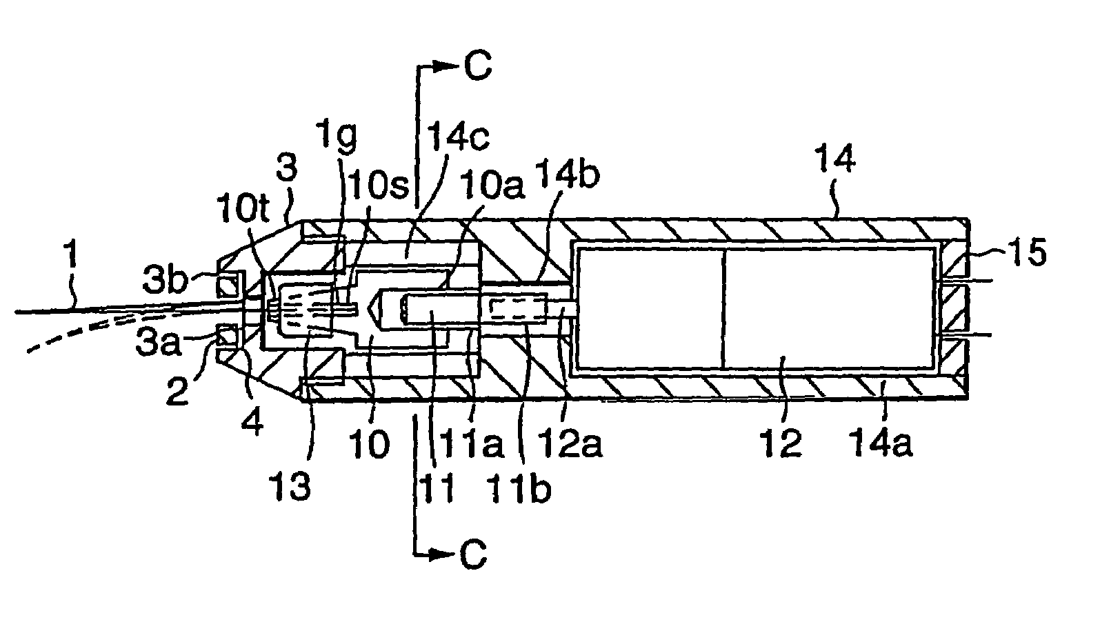
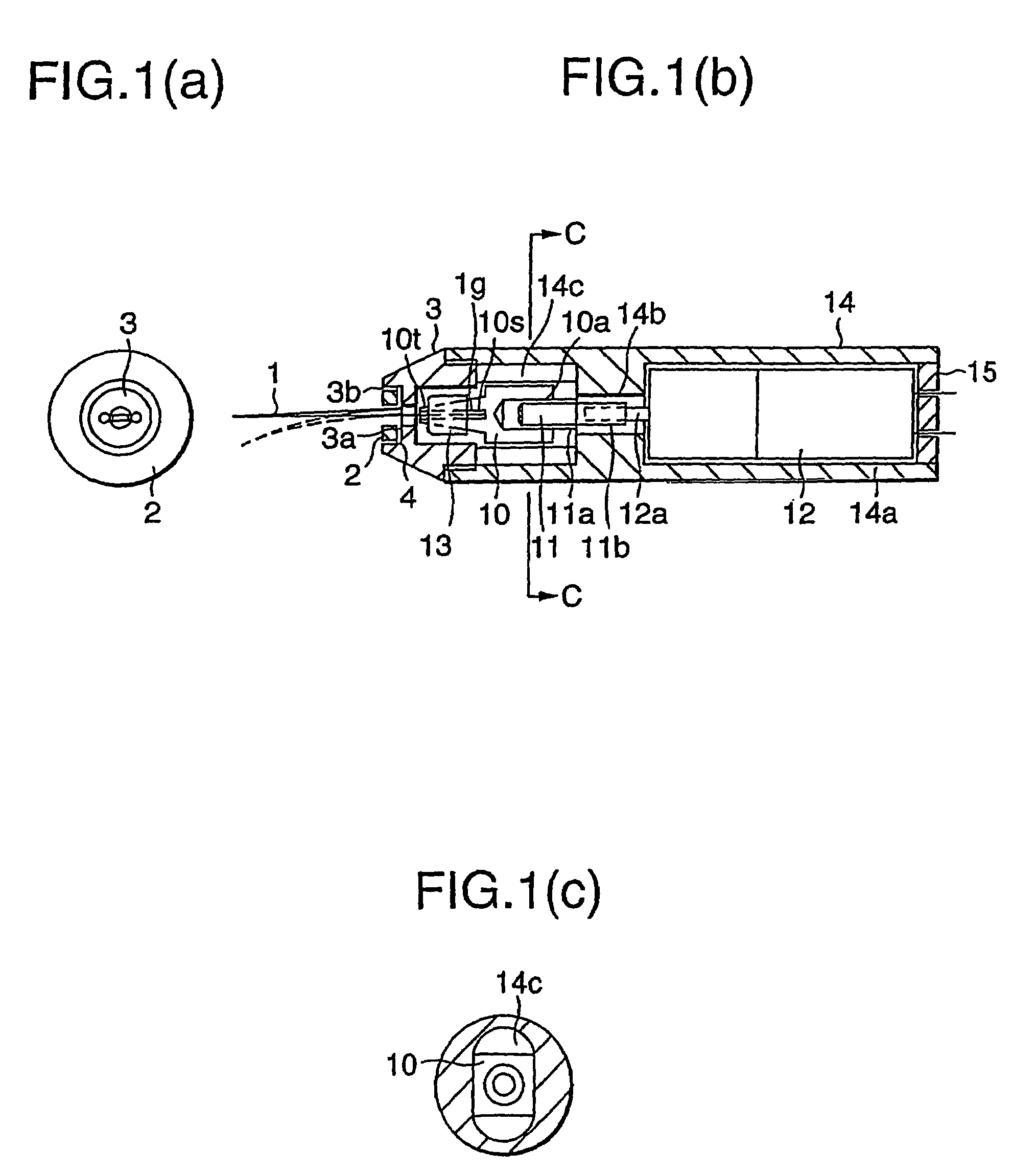
[0028]Referring to FIGS. 1 and 2, a description will be given of an embodiment of the invention. FIG. 1 is cross-sectional views and a side elevational view of an actuator, and FIG. 2 is a perspective view of a plate-shaped displacement enlarging member.
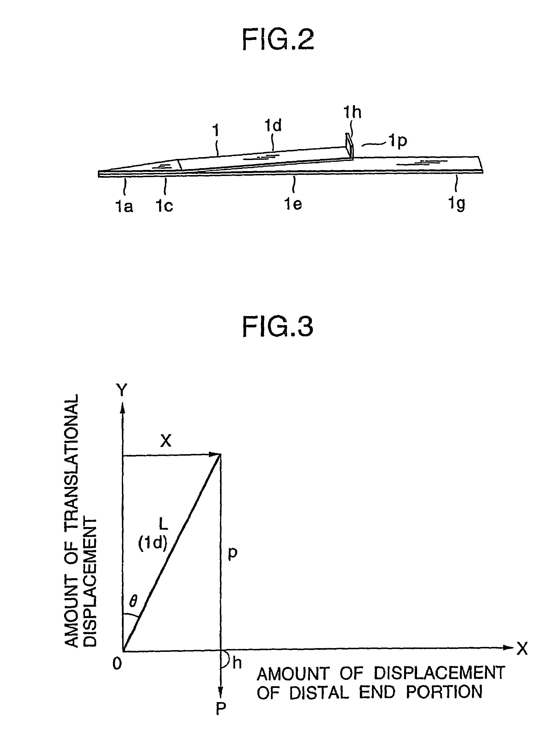
[0029]In FIGS. 1 and 2, the actuator is comprised of an operating finger 1 serving as a substantially V-shaped displacement enlarging member whose distal end portion undergoes enlarging displacement on the basis of translational displacement so as to operate on a very small object; a drive section for imparting a driving force on the operating finger 1 by rotating; a converting section for converting the rotation of this drive section to translational movement; a connecting section for connecting this converting section and the operating finger 1; a case section for accommodating the converting section, the drive section, and the connecting section; and a fixing section for fixing a portion of the operating finger 1 by making use of ...
second embodiment
[0053]Referring to FIGS. 6 and 7, a description will be given of another embodiment of the invention. FIG. 6 is a perspective view of the displacement enlarging member having a nipping portion, and FIG. 7 is a cross-sectional view of the actuator having the nipping portion. In the drawings, the same reference numerals as those of FIG. 1 denote identical or corresponding portions, and a description thereof will be omitted.
[0054]In FIGS. 6 and 7, this actuator differs from that of FIG. 1 only in the displacement enlarging member, the connecting section, and the fixing section, so that a description will be given of such arrangements. First, a pair of gripper fingers 21 serving as the displacement enlarging member is made of a beam-like member formed substantially in an M-shape and having a spring characteristic. The pair of gripper fingers 21 is formed just as if the ends 1g of two operating fingers 1, one being shown in FIG. 2, are integrated in common, an apex portion 21c is provide...
third embodiment
[0062]Referring to FIGS. 11 and 12, a description will be given of still another embodiment of the invention. FIG. 11 is a cross-sectional view of the nut, and FIG. 12 is a perspective view of the threaded shaft which is threadedly engaged with the nut shown in FIG. 11. In this actuator, only the nut 10 and the threaded shaft 11 shown in FIG. 1 are different, and a translational-displacement-amount limiting portion is provided to limit the amount of the translational displacement of the operating (gripper) finger(s).
[0063]In FIGS. 11 and 12, the translational-displacement-amount limiting portion consists of a nut 110 and a threaded shaft 111 serving as a transmitting member which is threadedly engaged with the nut 110. The nut 110 has in its cut hollow portion 110a of a substantially cylindrical shape a limiting nut 151 which is engaged and fixed there in for limiting the translational movement. The limiting nut 151 with an internal thread formed therein as well as the threaded shaf...
PUM
 Abstract
Description
Claims
Application Information
 - R&D
- Intellectual Property
- Life Sciences
- Materials
- Tech Scout
- Unparalleled Data Quality
- Higher Quality Content
- 60% Fewer Hallucinations
Browse by: Latest US Patents, China's latest patents, Technical Efficacy Thesaurus, Application Domain, Technology Topic, Popular Technical Reports.
© 2025 PatSnap. All rights reserved.Legal|Privacy policy|Modern Slavery Act Transparency Statement|Sitemap|About US| Contact US: help@patsnap.com


