Photographic flashlight

a flashlight and photoelectric technology, applied in the field of photoelectric devices, can solve the problems of unsuitable or optimal lighting effect of the flashlight, low or too high flashing, and objects being shot that are not properly illuminated, and achieve the effect of optimal lighting effect of the photographic devi

Inactive Publication Date: 2009-05-12
WHANG STUART A
View PDF4 Cites 51 Cited by
  • Summary
  • Abstract
  • Description
  • Claims
  • Application Information

AI Technical Summary

Benefits of technology

[0010]A main object of the present invention is to provide a light diffusion arrangement for a photographic device having a flashlight, wherein the light diffusion arrangement is capable of diffracting and diffusing flashes produced by the flashlight for generating an optimal lighting effect for the photographic device.
[0011]Another object of the present invention is to provide a light diffusion arrangement for a photographic device having a flashlight, wherein the light diffusion arrangement is adapted to maximize the period in which soft and uniform flashes are produced to illuminate a targeted object.
[0013]Another object of the present invention is to provide a light diffusion arrangement for a photographic device having a flashlight, wherein the light diffusion arrangement does not involve complicated manufacturing procedures so as to minimize the manufacturing cost of the present invention.
[0017]a plurality of light diffusing elements integrally formed on an outer side surface of the surrounding sidewall of the diffuser housing, wherein the diffracted light is arranged to impinge on the light diffusing elements from the light diffraction cavity, in such a manner that each of the light diffusing elements is adapted to diverge the diffracted light for diffusing the diffracted light, so as to provide a uniform light diffusion effect as an optimal lighting effect for the photographic device.

Problems solved by technology

As a matter of fact, there are several disadvantages in relation to conventional flashlights.
For example, the flashes produced by conventional flashlights may be too short or too long in time so that the objects being shot are not properly illuminated.
Similarly, the intensity of the flashes may be too low or too high such that the illumination produced by the flashlights is not suitable or optimal for the particular purposes for which the flashlights are utilized.
The problem with this conventional device is that the light extractor-diffuser is inflexible in that the diffusion of light is largely due to the geometry of the diffuser, notable the several triangular panels, and the trapezoidal panel thereof.
What matters is that diffusers of different angles require different manufacturing equipments and this substantially increases the relevant manufacturing cost.
It does not, however, address the problems for conventional flashlights as described above.
Now the problem with this invention is that while the diffuser may work fairly well for producing a studio-quality lighting performance, it is certainly not ideal for producing an adequately long-lasting flashing effect.
While this is theoretically possible, it is not feasible or even desirable in practice.
This is because when the illumination time of the light source is lengthened, the overall aesthetic effect of the photograph may be undesirably altered in addition to what is expected from prolonging the illumination time of the light source.
Finally, a general problem about conventional light diffusers: almost all conventional light diffusers fail to achieve a satisfactorily uniform lighting performance.
This is partly due to the fact that the geometry of the cowl or the flash housing does not match with the physical nature of light propagation.

Method used


Image

  • Photographic flashlight
  • Photographic flashlight
  • Photographic flashlight

Examples


Embodiment Construction

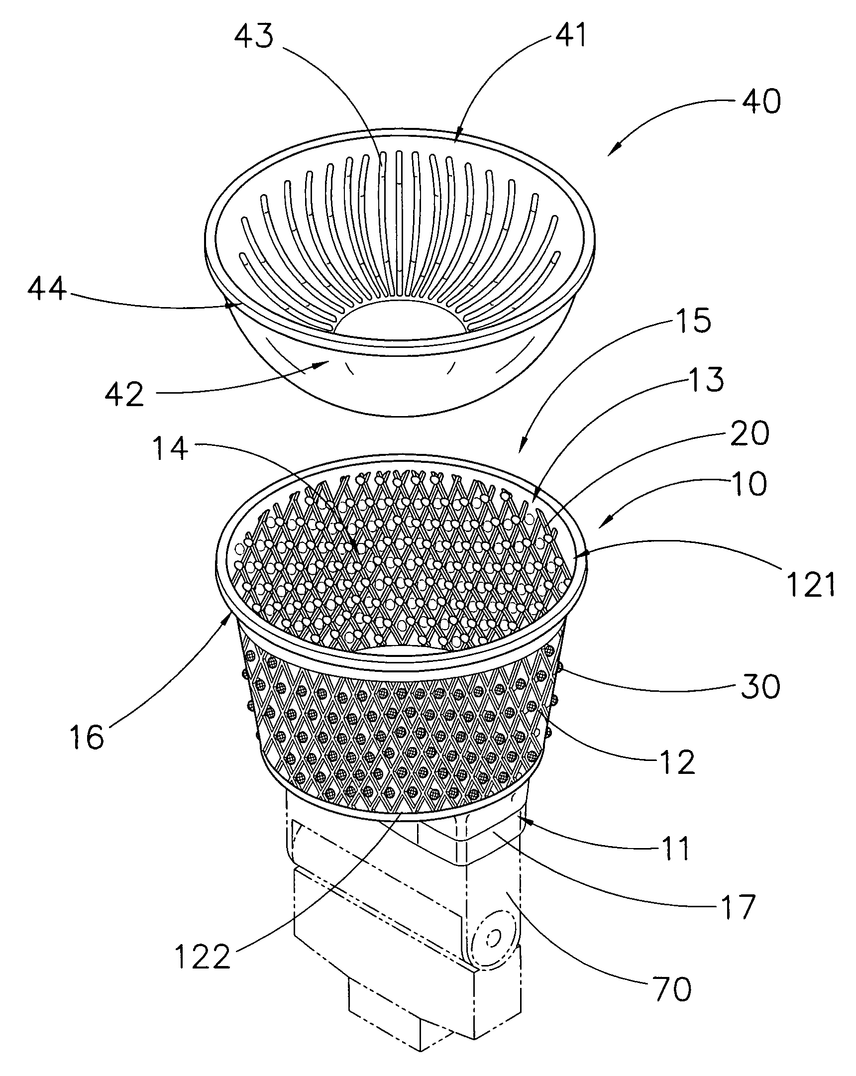
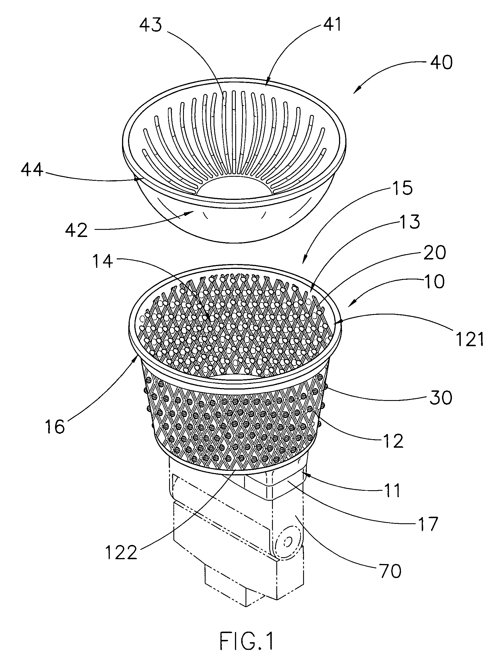
[0022]Referring to FIG. 1 to FIG. 3 of the drawings, a light diffusion arrangement according to a preferred embodiment of the present invention is illustrated. The light diffusion arrangement is for a photographic device having a flashlight 70, and comprises a diffuser housing 10, a plurality of diffracting meshes 20, and a plurality of light diffusing elements 30.

[0023]The diffuser housing 10 has a base portion 11 for mounting with the flashlight 70 of the photographic device, and a light-admissible surrounding sidewall 12 extended from the base portion 11 to define a light diffraction cavity 13 within the base portion 111 and the surrounding sidewall 12.

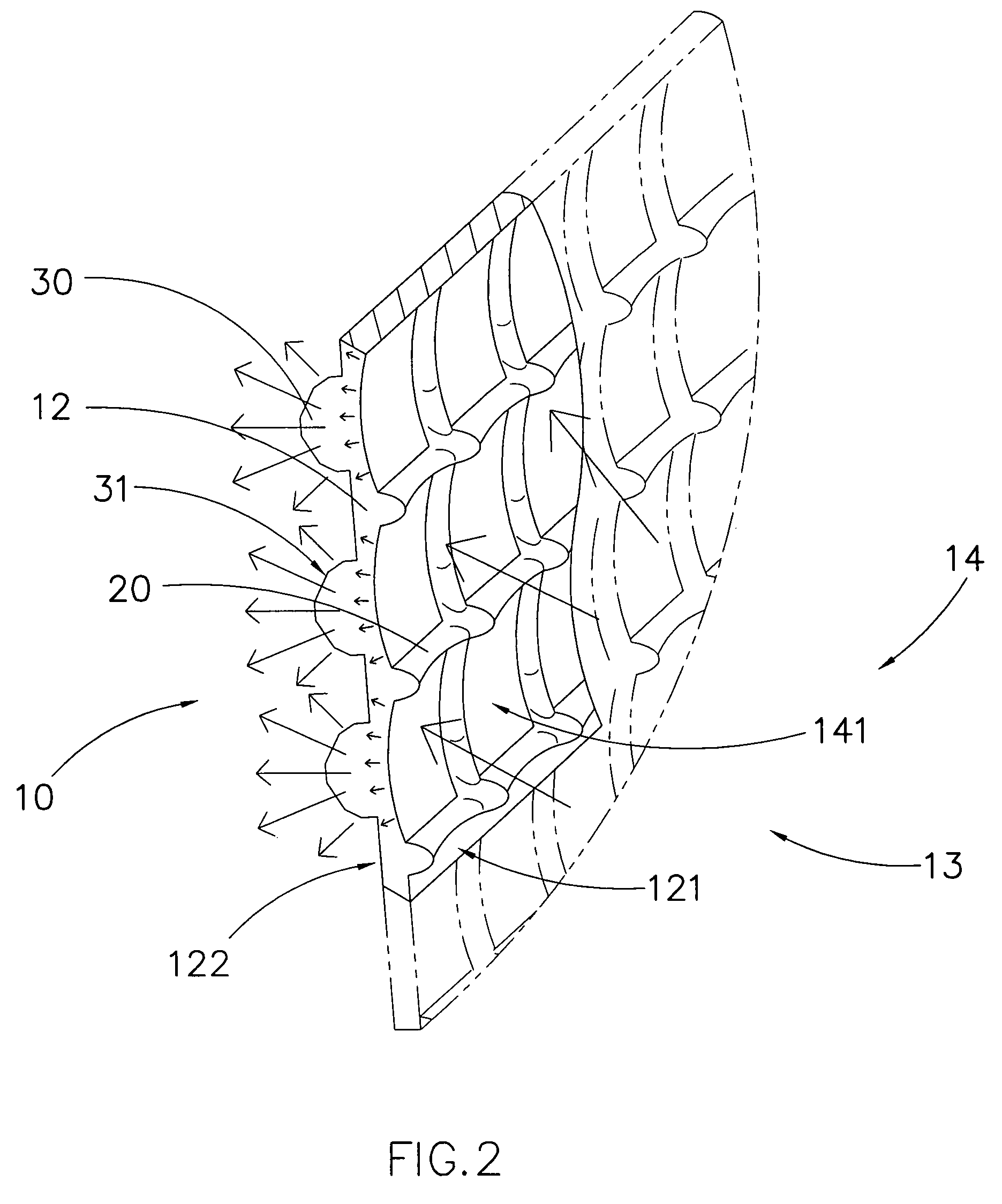
[0024]The plurality of diffracting mesh members 20 is formed on an inner side surface 121 of the surrounding sidewall 12 of the diffuser housing 10, wherein each of the diffracting mesh members 20 is adapted to diffract light impinging thereon to a predetermined direction within the light diffraction cavity 13.

[0025]The plurality o...


PUM


Abstract

A light diffusion arrangement, for a photographic device having a flashlight, includes a diffuser housing, a plurality of diffracting mesh members, and a plurality of light diffusing elements. The diffuser housing has a light-admissible surrounding sidewall radially extended from a base portion to define a light diffraction cavity. The diffracting mesh members are integrally formed on an inner side surface of the surrounding sidewall of the diffuser housing, while the light diffusing elements are integrally formed on an outer side surface of the surrounding sidewall of the diffuser housing, wherein the diffracted light is arranged to impinge on the light diffusing elements from the light diffraction cavity, in such a manner that each of the light diffusing elements is adapted to diverge the diffracted light for diffusing the diffracted light, so as to provide a uniform light diffusion effect as an optimal lighting effect for the photographic device.

Description

BACKGROUND OF THE PRESENT INVENTION[0001]1. Field of Invention[0002]The present invention relates to a photographic device, and more particularly to a photographic flashlight which is capable of producing flashes which is suitably diffused and diffracted for achieving an optimal photographic performance.[0003]2. Description of Related Arts[0004]A conventional flashlight usually comprises a light source which is capable of producing high-intensity flashlight, and a flash housing for securely mounting the light source. The flash housing is then mounted onto a wide variety of devices, such as cameras, for providing flashes for particular purposes, such as providing adequate illumination when the camera is taking pictures.[0005]As a matter of fact, there are several disadvantages in relation to conventional flashlights. For example, the flashes produced by conventional flashlights may be too short or too long in time so that the objects being shot are not properly illuminated. Similarly...

Claims


Application Information

Patent Timeline
Patent Type & Authority Patents(United States)
IPC IPC(8): G03B15/06
CPCG03B15/02
Inventor CHAN-WING, LAWRENCE NG
Owner WHANG STUART A
Why Eureka
Try Eureka