Method and system for the directional detection of electrons in a scanning electron microscope

a scanning electron microscope and electron directional detection technology, applied in the field of scanning electron microscope system for directional detection of electrons, can solve the problem of complex detection system of secondary electrons

Inactive Publication Date: 2009-05-12
POLITECHNA WROCLAWSKA
View PDF20 Cites 12 Cited by
  • Summary
  • Abstract
  • Description
  • Claims
  • Application Information

AI Technical Summary

Benefits of technology

[0011]It is advantageous when each scintillator is positively biased against the output of the microporous plate with a high voltage of the value over 1000V.
[0012]It is also advantageous when the screen pipe placed in the hole of the microporous plate is negatively biased against the lower throttling aperture.
[0013]The main advantage of the electron detector system according to the invention is the possibility of the directional detection of secondary electrons in order to obtain output signals that are dependent on a local azimuth and slope angle of the surface examined. The output signals may be processed to obtain a three-dimensional reconstruction of the sample surface.

Problems solved by technology

However, the detector system for secondary electrons is much more complex.

Method used


Image

  • Method and system for the directional detection of electrons in a scanning electron microscope
  • Method and system for the directional detection of electrons in a scanning electron microscope
  • Method and system for the directional detection of electrons in a scanning electron microscope

Examples


first embodiment

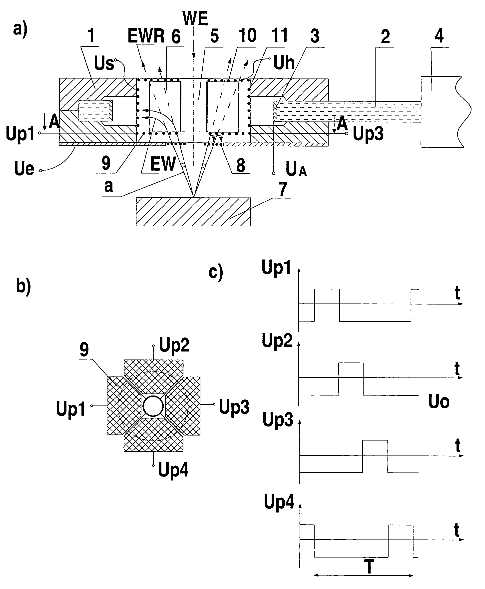
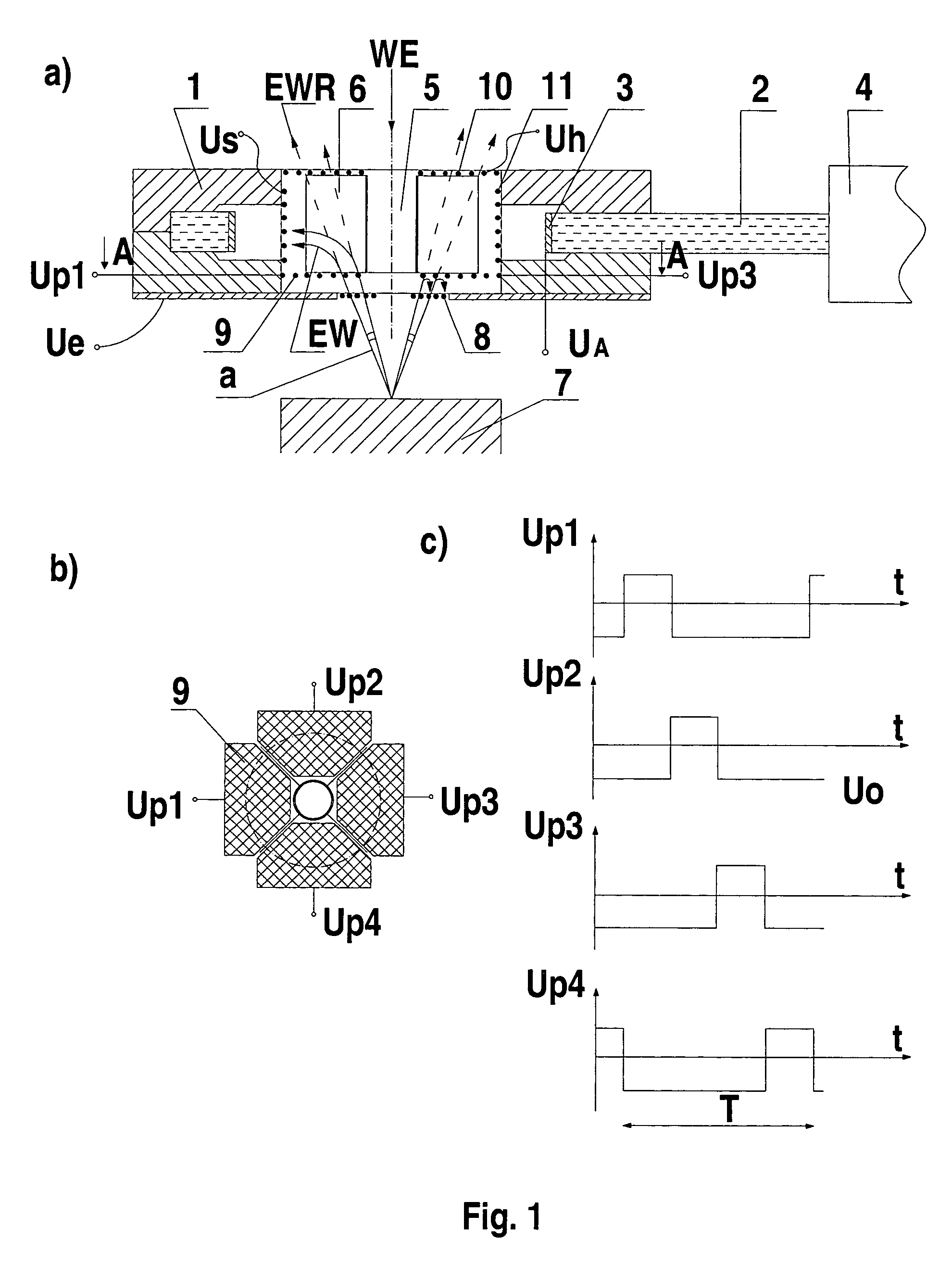
[0026]the invention will now be described with reference to FIGS. 1a to 1c.

[0027]The system for a directional detection of electrons in a scanning electron microscope shown in FIG. 1a is mounted in a ring-shaped head body 1 made of teflon. A light conductor or light pipe 2 is located in a slot of the two-piece head body 1 and is in the form of a plexiglass plate with an opening covered with a scintillator 3 on its perimeter. The light pipe 2 is connected to a photomultiplier 4. Inside the head body 1, a screen pipe 5 is located with four screen plates 6 attached symmetrically which divide a hole in the head body 1 into four sectors. In a lower part of the head body 1, on a side of the head body facing toward a sample stage 7, an input grid 8 is located. Above the input grid 8, four sector electron flow control electrodes 9 are located and each one is placed in one sector formed between the screen plates 6. The sector flow control electrodes 9 each are made of a metal grid. A retard...

second embodiment

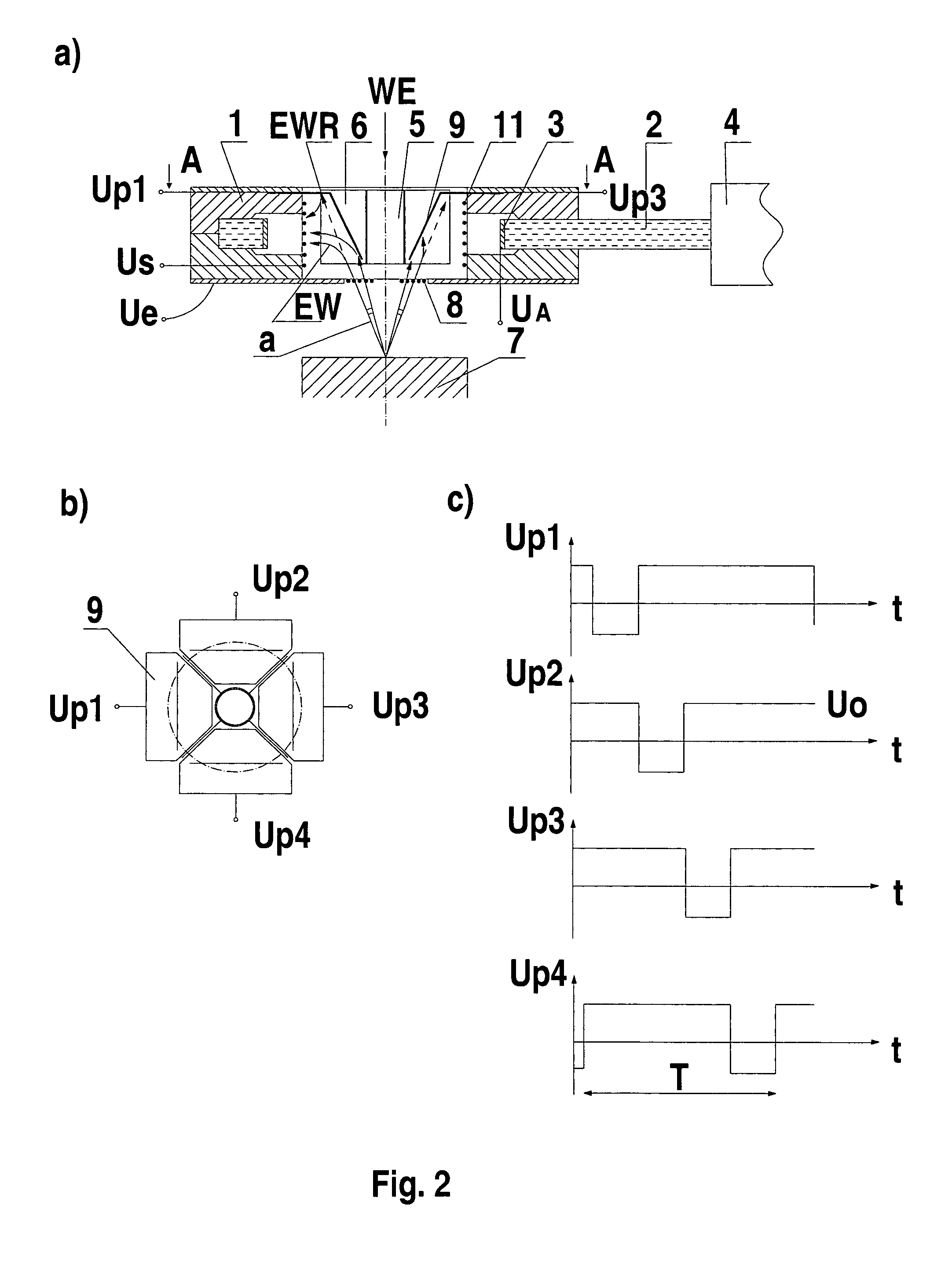
[0030]the invention will now be described with reference to FIGS. 2a to 2c.

[0031]The system for the directional detection of electrons in a scanning electron microscope shown in FIG. 2a is designed similarly to the first embodiment and is mounted in a ring-shaped head body 1 made of teflon. A light conductor or light pipe 2 is located in a slot of the two-piece head body 1 and is in the form of a plexiglass plate with a hole covered with a scintillator 3 on its perimeter. The light pipe 2 is connected to a photomultiplier 4. A screen pipe 5 with four screen plates 6 divides the hole in the head body 1 interior into four sectors. An input grid 8 is located in a lower part of the head body 1 on a side of the head body facing toward a sample stage 7. Electron flow control electrodes 9 are located above the input grid 8 in the upper part of the head body 1 with each one of the electron flow control electrodes being placed in one sector formed between the screen plates 6. The sector flo...

third embodiment

[0035]the invention will now be described with reference to FIGS. 3a to 3d.

[0036]- - The system for the directional detection of electrons in a scanning electron microscope shown in FIG. 3a is adapted to operate in a low vacuum scanning electron microscope. The unit is mounted in a head body 1, made of teflon. A lower throttling aperture 12 is located in the lower part of the head body 1 facing toward a sample stage 7 and formed as a metal plate with a small hole. The hole is coaxial with the axis of the primary electron beam WE. A microporous plate 13 is located above the lower throttling aperture 12. An O-ring seal 20 is interposed between head body 1 and the microporous plate 13. The microporous plate 13 has a hole also coaxial with the axis of the primary electron beam WE. Inside the mircroporous plate 13, a screening pipe 5 is fixed by means of a teflon seal. A lower entrance surface of the microporous plate 13 which faces toward the sample stage is coated with a thin conducti...


PUM


Abstract

A system detects electrons according to their emission direction in a scanning electron microscope. The system includes a scintillator electron detector and a set of electrodes focusing and controlling the electron flow. At least in two sectors of the electron flow from the sample stage (7) to the scintillator (3), sector flow control electrodes (9) are placed and supplied alternatively with electric pulses. The sector flow control electrodes (9) may be made of a metal grid or in a shape of conducting plates or deposited on the surface of a microporous plate in the form of a thin conductive layer.

Description

CROSS REFERENCE TO RELATED APPLICATIONS[0001]This is a continuation-in-part application of international patent application PCT / PL 2004 / 000079, filed Oct. 6, 2004, claiming priority from Polish application 363131, filed Oct. 27, 2003, and a continuation-in-part application of international patent application PCT / PL 2004 / 000080, filed Oct. 6, 2004, and claiming priority from Polish application 364510, filed Jan. 21, 2004, and the entire content of all applications is incorporated herein by reference.FIELD OF THE INVENTION[0002]The invention relates to a system for the directional detection of electrons in a scanning electron microscope, particularly destined to obtain topographic contrast of images of a sample surface or to enable its three dimensional reconstruction. Some embodiments of the system are destined particularly for the work at pressures in the order of 100 Pa in the sample chamber.BACKGROUND OF THE INVENTION[0003]-- There are systems for the directional detection of elec...

Claims


Application Information

Patent Timeline
Patent Type & Authority Patents(United States)
IPC IPC(8): H01J37/244
CPCH01J37/244H01J2237/2443H01J2237/2446H01J2237/2605
Inventor SLOWKO, WITOLD
Owner POLITECHNA WROCLAWSKA
Why Eureka
Try Eureka