
Method of encapsulating a display element with frit wall and laser beam

a display element and frit wall technology, applied in the manufacture of electrode systems, cold cathode manufacturing, electric discharge tube/lamp manufacture, etc., can solve the problems of frit and/or substrate cracking, difficult to develop sealing processes, and easy degradation of the display elemen

Inactive Publication Date: 2009-05-26
CORNING INC
View PDF64 Cites 59 Cited by
  • Summary
  • Abstract
  • Description
  • Claims
  • Application Information

AI Technical Summary

Problems solved by technology

However, OLED displays, and in particular the electrodes and organic layers located therein, are susceptible to degradation resulting from interaction with oxygen and moisture leaking into the OLED display from the ambient environment.
Unfortunately, in the past it has been very difficult to develop a sealing process to hermetically seal the OLED display.
Nevertheless, without adequate cooling of the heated frit (and substrates), cracking of the frit and / or substrates can occur due to thermal stresses generated during the sealing process.

Method used


Image

  • Method of encapsulating a display element with frit wall and laser beam
  • Method of encapsulating a display element with frit wall and laser beam
  • Method of encapsulating a display element with frit wall and laser beam

Examples


Embodiment Construction

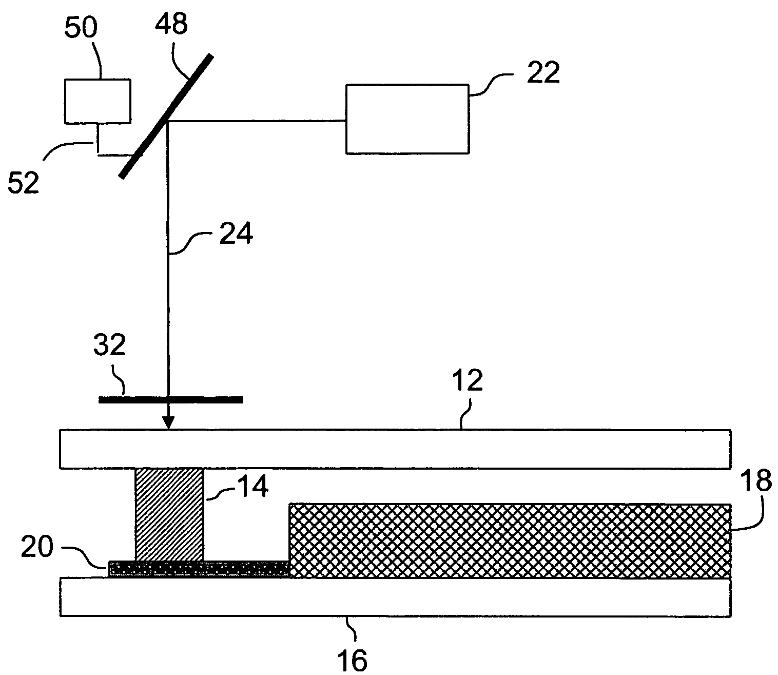
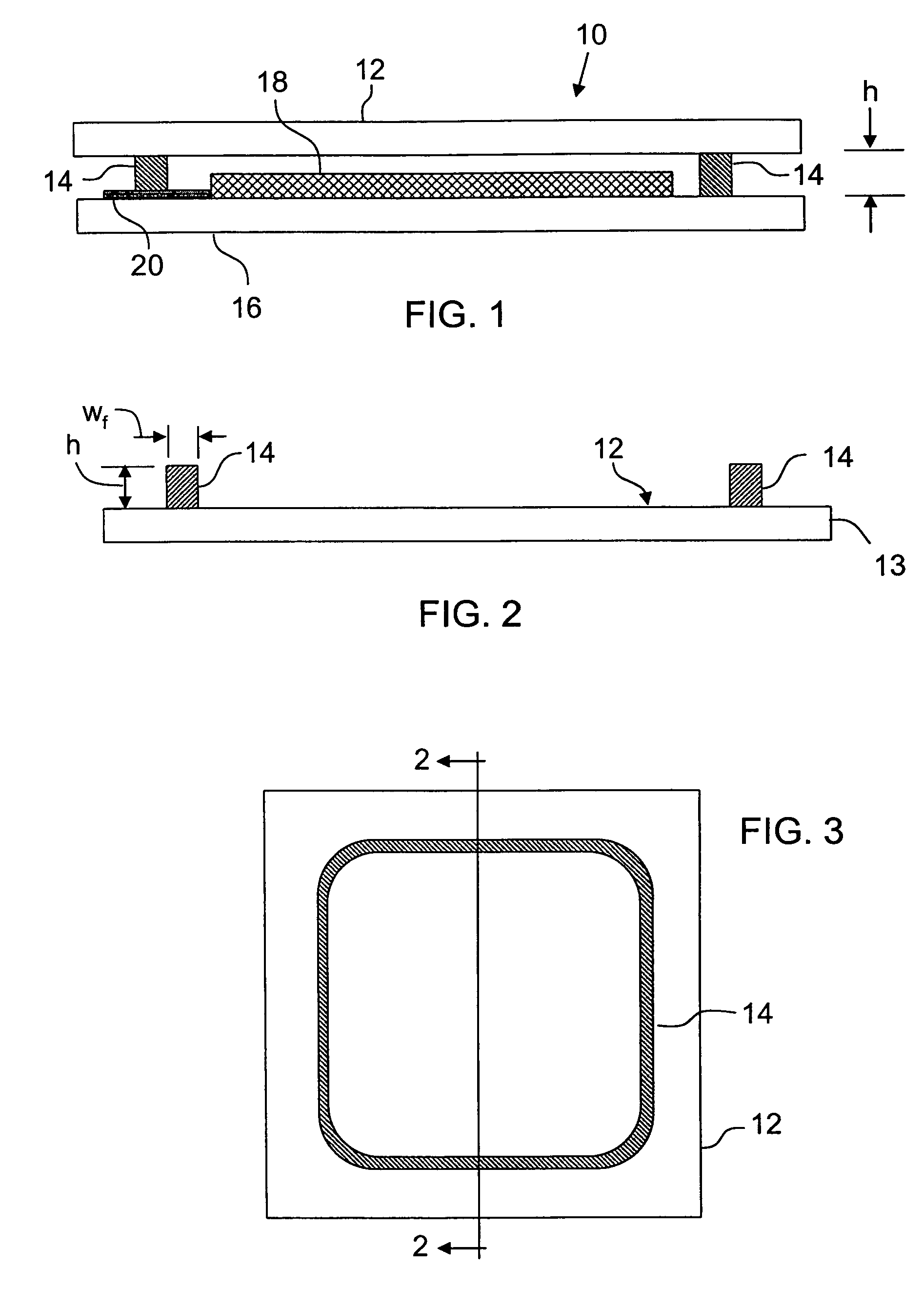
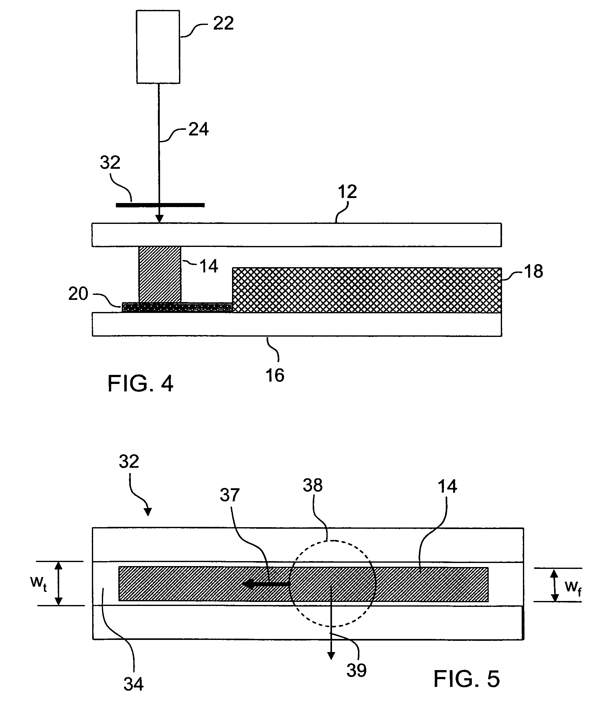
[0023]In the following detailed description, for purposes of explanation and not limitation, example embodiments disclosing specific details are set forth to provide a thorough understanding of the present invention. However, it will be apparent to one having ordinary skill in the art, having had the benefit of the present disclosure, that the present invention may be practiced in other embodiments that depart from the specific details disclosed herein. Moreover, descriptions of well-known devices, methods and materials may be omitted so as not to obscure the description of the present invention. Finally, wherever applicable, like reference numerals refer to like elements.

[0024]Although the sealing techniques of the present invention are described below with respect to manufacturing a hermetically sealed OLED display, it should be understood that the same or similar sealing techniques can be used to seal two glass plates to one another that can be used in a wide variety of applicati...


PUM


Abstract

A method of minimizing stress in an OLED device laser sealing process using an elongated laser beam. A laser beam having an intensity distribution which decreases as a function of distance from the longitudinal axis of the beam is passed through a mask to create an elongated beam having a length-wise intensity distribution which decreases as a function of distance from the axis of the beam and a substantially constant width-wise intensity distribution. The elongated beam is traversed over a line of frit disposed between two substrates. The tails of the length-wise intensity distribution provide for a slow cool down of the frit as the beam traverses the line of frit.

Description

[0001]This application claims the benefit of priority under 35 U.S.C. § 119(e) of U.S. Provisional Application Ser. No. 60 / 748,297 filed on Dec. 6, 2005, the content of which is incorporated herein in its entirety by reference.BACKGROUND OF THE INVENTION[0002]1. Field of the Invention[0003]This invention is directed to a method for encapsulating a display element such as are used for glass substrates for flat panel display devices.[0004]2. Technical Background[0005]Organic light emitting diodes (OLEDs) have been the subject of considerable research in recent years because of their use and potential use in a wide variety of electroluminescent devices. For instance, a single OLED can be used in a discrete light emitting device or an array of OLEDs can be used in lighting or flat-panel display applications (e.g., OLED displays). OLED flat panel displays in particular are known to be very bright and to have good color contrast and wide viewing angle. It is well known that the life of th...

Claims


Application Information

Patent Timeline
Patent Type & Authority Patents(United States)
IPC IPC(8): H01J9/24H01J9/26
CPCH01L51/5237H01L51/56H10K50/8426H10K71/00H05B33/04H05B33/10
Inventor BECKEN, KEITH JAMESLOGUNOV, STEPHAN LVOVICH
Owner CORNING INC
Learn More